Description
Overview
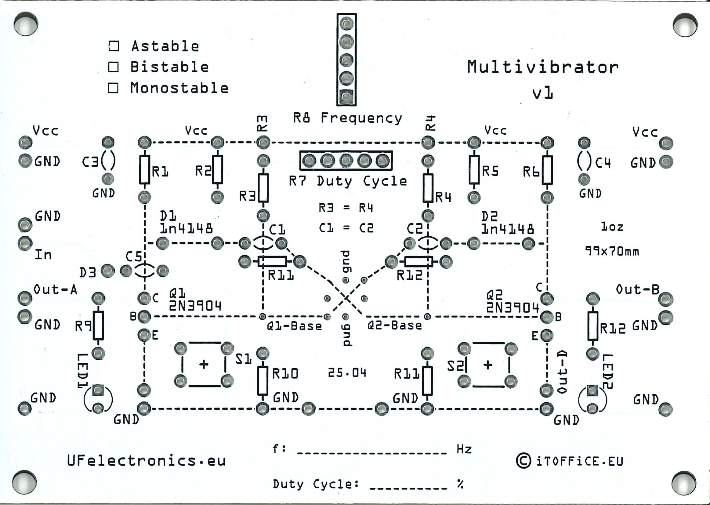
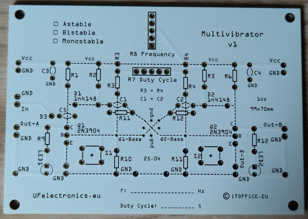
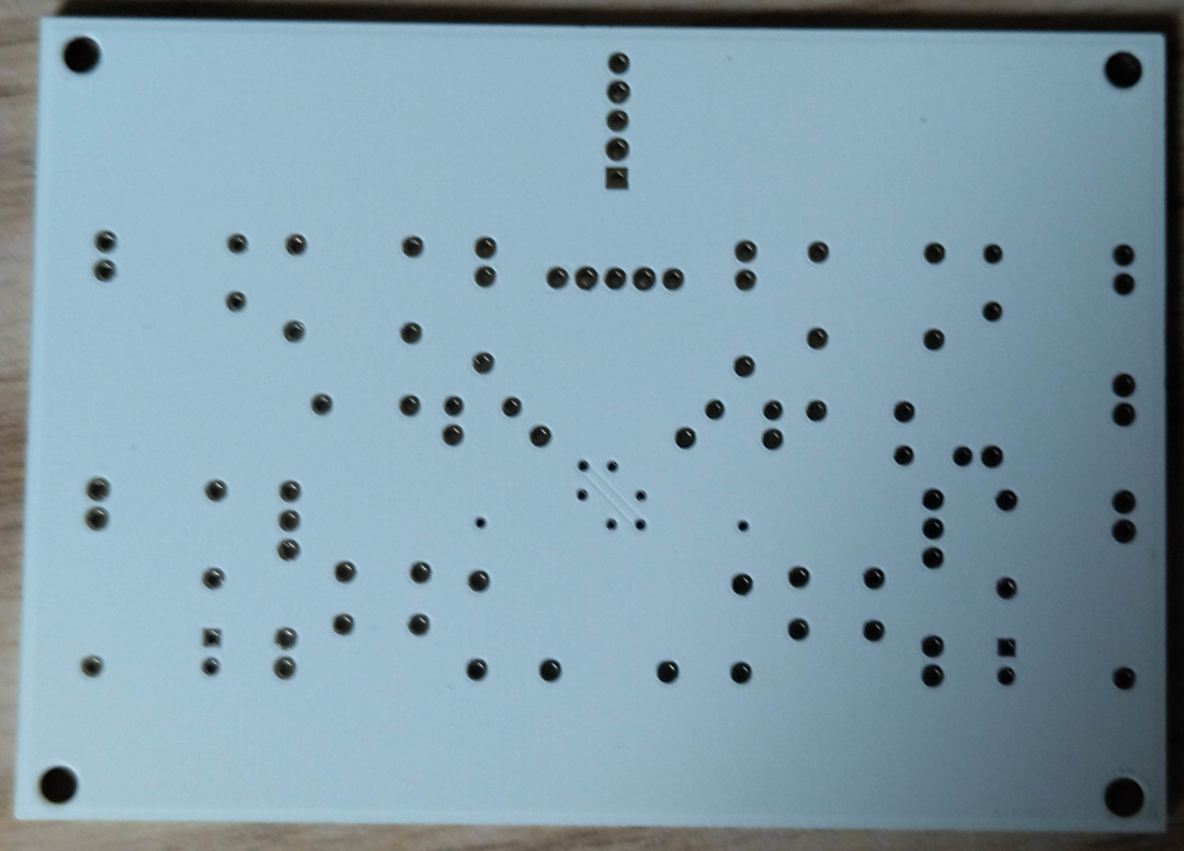
The Transistor Multivibrator Experimentation Board is a reusable learning and prototyping platform designed for building, modifying, and understanding classic transistor timing circuits.
Unlike solderless breadboards where wiring errors are common, the PCB provides a structured layout that makes experimenting with discrete transistor multivibrators faster, cleaner, and easier to understand.
The board supports everything from simple blinking LED circuits to pulse generators, flip-flops, timing circuits, and frequency dividers using standard through-hole components.
Its semi-schematic PCB layout makes the signal flow easy to follow while leaving plenty of flexibility for modifications and custom experiments.
Features
- Build Astable, Monostable and Bistable multivibrators
- Supports both symmetrical and asymmetrical oscillators
- Easy experimentation with RC timing networks
- Optional frequency adjustment using potentiometers
- Variable duty-cycle experiments
- Frequency divider configurations
- Toggle (flip-flop) circuits
- Pulse generation and pulse stretching
- Two anti-phase outputs for astable circuits
- Easy oscilloscope probing points
- Through-hole components for education and rapid modification
- Semi-schematic PCB layout for easier circuit understanding
- Large ground plane for improved signal integrity
Educational Value
The board is designed to help students understand:
- Positive feedback
- Regenerative switching
- RC timing
- Capacitor charging and discharging
- Exponential charging curves
- Transistor saturation
- Transistor cut-off
- Pulse generation
- Oscillator design
- Flip-flop operation
- Frequency division
- Duty-cycle control
- Square-wave generation
- Timing calculations
- Signal propagation
- Analog-to-digital transition concepts
What can be built?
The board supports experiments such as:
- LED flashers
- Clock generators
- Pulse generators
- One-shot timers
- Toggle switches
- Memory latches
- Frequency dividers
- Duty-cycle generators
- Two-phase clock generators
- Pulse delay circuits
- Push-button debounce circuits
- Simple digital logic building blocks
Learning Journey
The board is intended to guide students through increasingly advanced transistor timing circuits.
A typical progression could be:
- Understanding transistor switching
- RC charging and discharging
- Basic astable multivibrator
- Measuring oscillation frequency
- Calculating timing constants
- Variable frequency oscillators
- Variable duty-cycle oscillators
- Monostable one-shot circuits
- Pulse stretching
- Bistable flip-flops
- Frequency dividers
- Toggle circuits
- Digital timing applications
- Custom multivibrator designs
Suitable For
- Electronics students
- Technical colleges
- Universities
- Makerspaces
- STEM education
- Hobbyists
- Engineering laboratories
- Analog electronics enthusiasts
- Digital electronics beginners
Why this board?
Transistor multivibrators are among the most important building blocks in electronics. Although modern integrated circuits often replace them in practical designs, understanding how they work provides valuable insight into transistor switching, timing, feedback, and the foundations of digital electronics.
By constructing these circuits from individual components, students can observe how resistor and capacitor values affect timing, how positive feedback creates rapid switching, and how stable and unstable states are established. These concepts form the basis of oscillators, timers, counters, memory elements, and many digital systems.
Suggestions for schematics, with many options:
* https://learnabout-electronics.org/Oscillators/osc41.php
* https://www.homemade-circuits.com/transistor-multivibrator-circuits-explained/