ufelectronics.eu
—
by
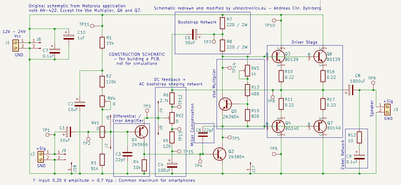
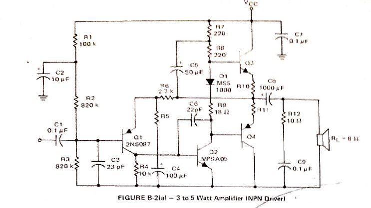
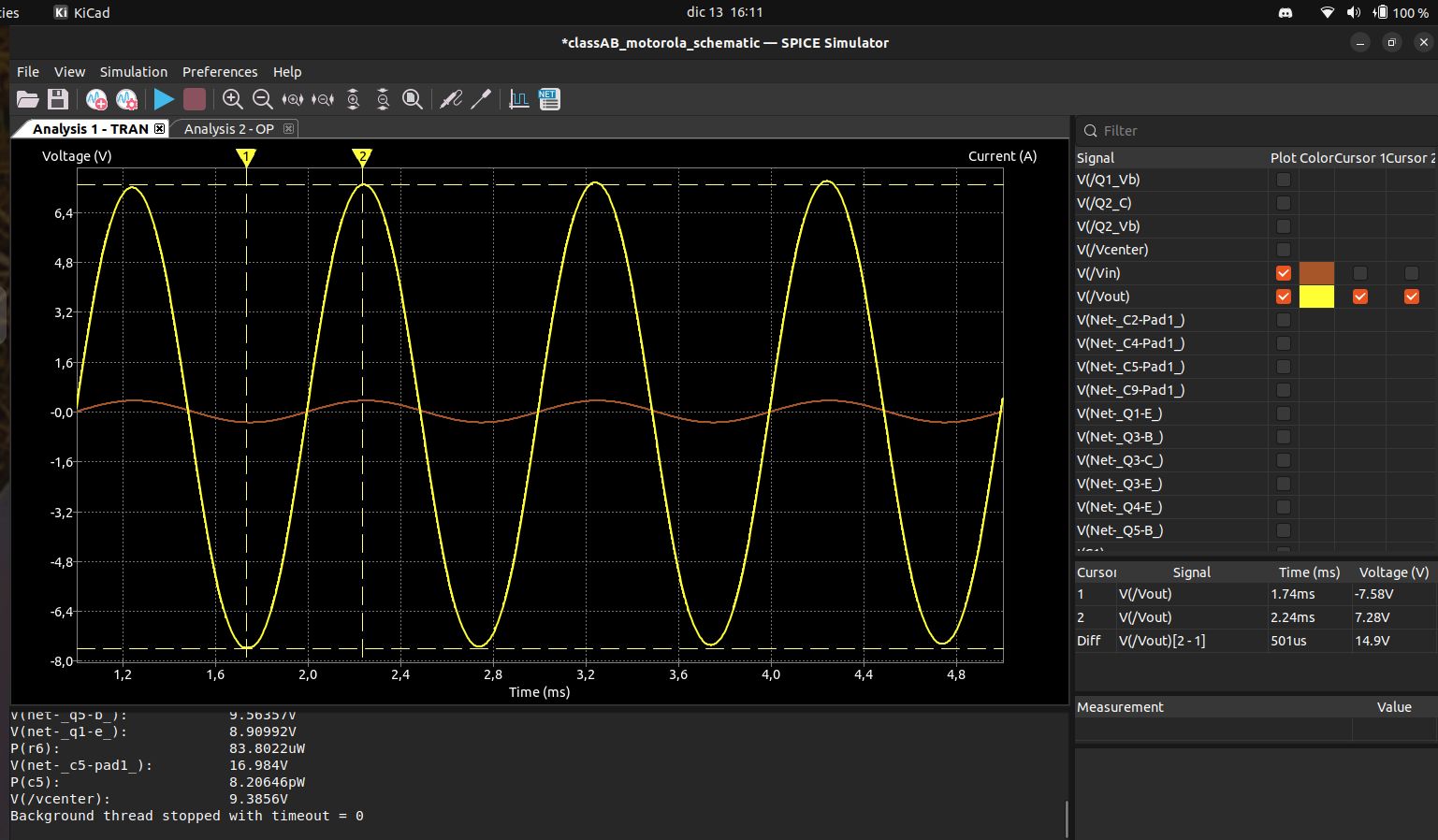
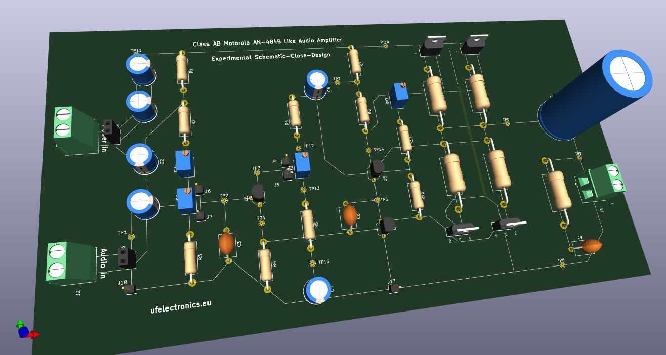
Build and experiment with the Motorola BJT Amp discussed on my LinkedIn profile back in November and December.
Download the KiCad files for free from my Github repo:
https://github.com/ufelectronics/classAB-motorola-PCB-layout
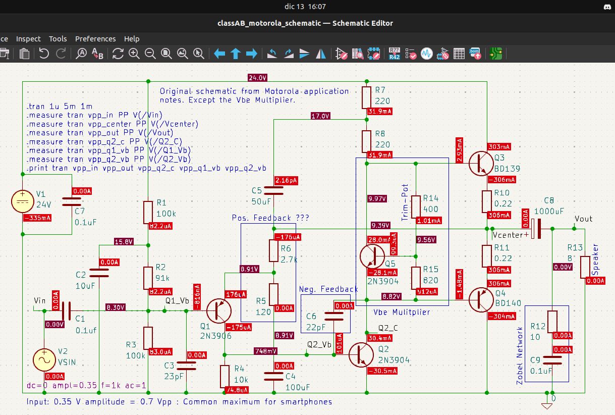
If you missed it, I once shared the KiCad file for simulating the Motorola AN-484A transistor amplifier.
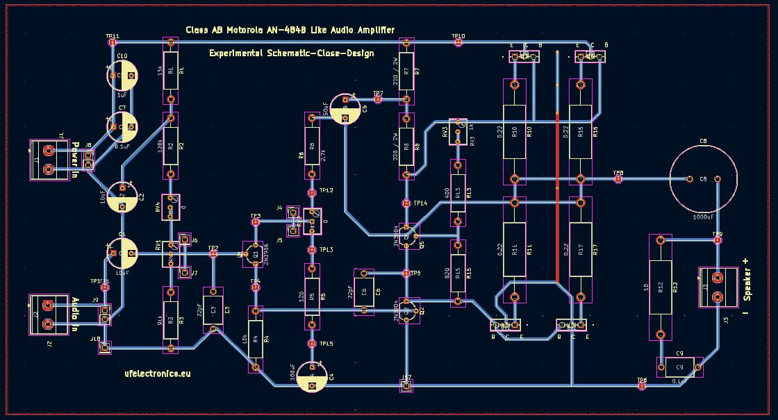
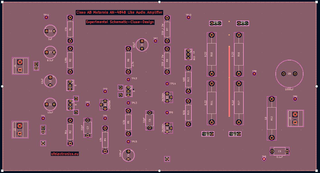
Now I’m sharing the KiCad files for making a PCB yourself.
* Integration of variable resistors (trimpots) – Make optimizations during testing – Faster results.
* Plenty of space around the components – Easier to measure at various points during testing.
* Through‑hole design, which makes it less demanding to build and therefore experiment‑ and beginner‑friendly.
* Schematic-Synchronized PCB Design – PCB design as it looks in the schematic, for easy mental switching.
This should guarantee easy experimentation, a fast outcome and way more fun. – An experience you’ll never forget!
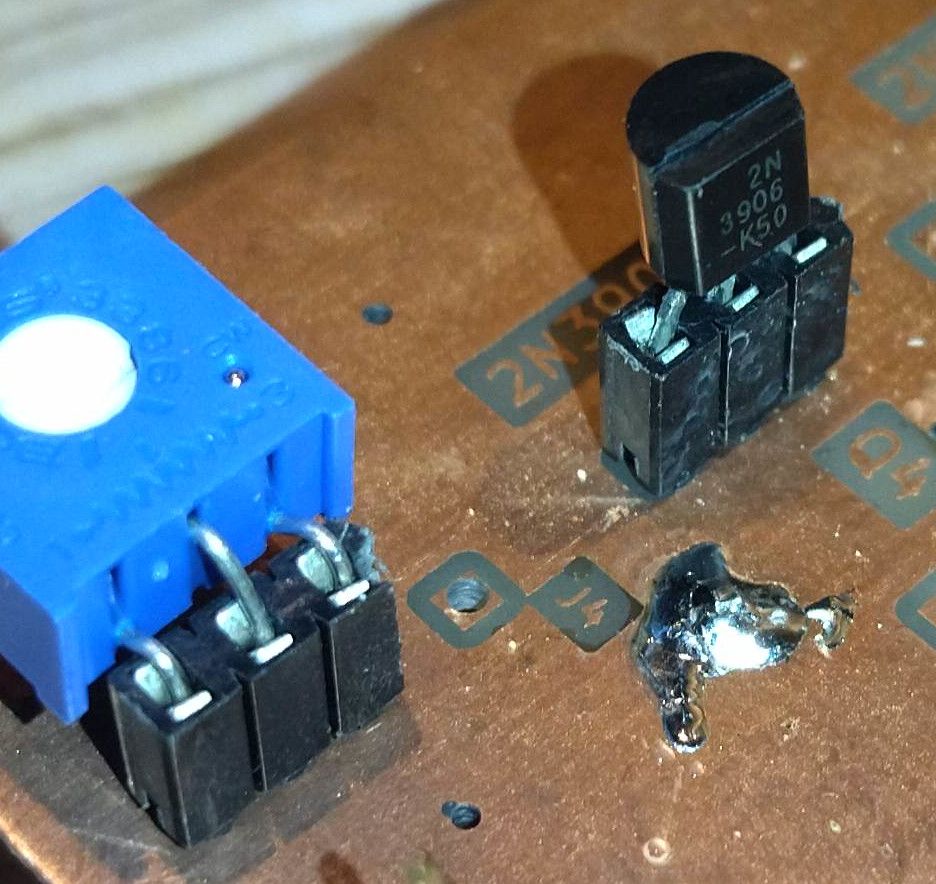
Use female pin headers at critical places instead of soldering the components directly onto the board. – This makes changes even easier and faster.
Your basket is currently empty!
Notifications
Build and experiment with the Motorola BJT Amp discussed on my LinkedIn profile back in November and December.
Download the KiCad files for free from my Github repo:
https://github.com/ufelectronics/classAB-motorola-PCB-layout
If you missed it, I once shared the KiCad file for simulating the Motorola AN-484A transistor amplifier.
Now I’m sharing the KiCad files for making a PCB yourself.
The PCB includes:
* Integration of variable resistors (trimpots) – Make optimizations during testing – Faster results.
* Plenty of space around the components – Easier to measure at various points during testing.
* Through‑hole design, which makes it less demanding to build and therefore experiment‑ and beginner‑friendly.
* Schematic-Synchronized PCB Design – PCB design as it looks in the schematic, for easy mental switching.
This should guarantee easy experimentation, a fast outcome and way more fun. – An experience you’ll never forget!
PRO TIP:
Use female pin headers at critical places instead of soldering the components directly onto the board. – This makes changes even easier and faster.