
Category: DIY
-
Testing v8.1 of the BJT Transistor Experimentation Board…
…with a Colpitts oscillator setup. – See the schematics in the images. Version 8.1 adds: * Optional Vcc+ supply filter using resistor, ferrite bead or inductor * Collector resistor split for gain boost experiments * Additional feedback network for common collector stages * Extra ground point for cleaner external feedback wiring Everything worked as expected.…
-
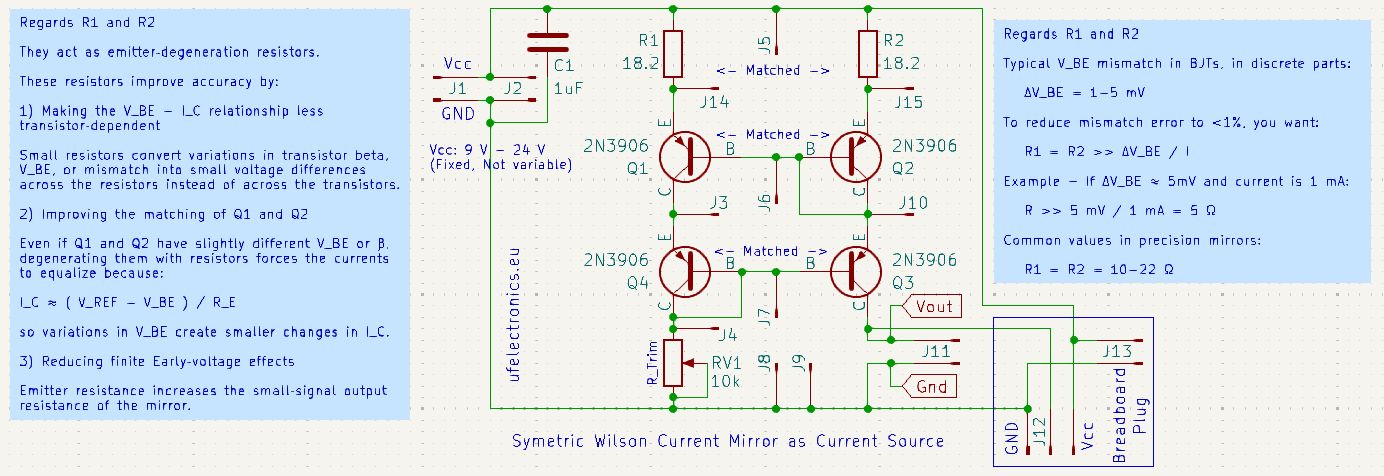
The Symmetric Wilson Current Mirror – Free KiCad PCB Design Files
Get the free Kicad PCB design files of the Symmetric Wilson Current Mirror – And start build your own for your DIY audio projects. Get the Kicad files from Github, and order where you want : (Both versions available. Future updates too.) https://github.com/ufelectronics/Symmetric_Wilson_Current_Mirror – Or order directly from PCBWay : (Plain version, without…
-
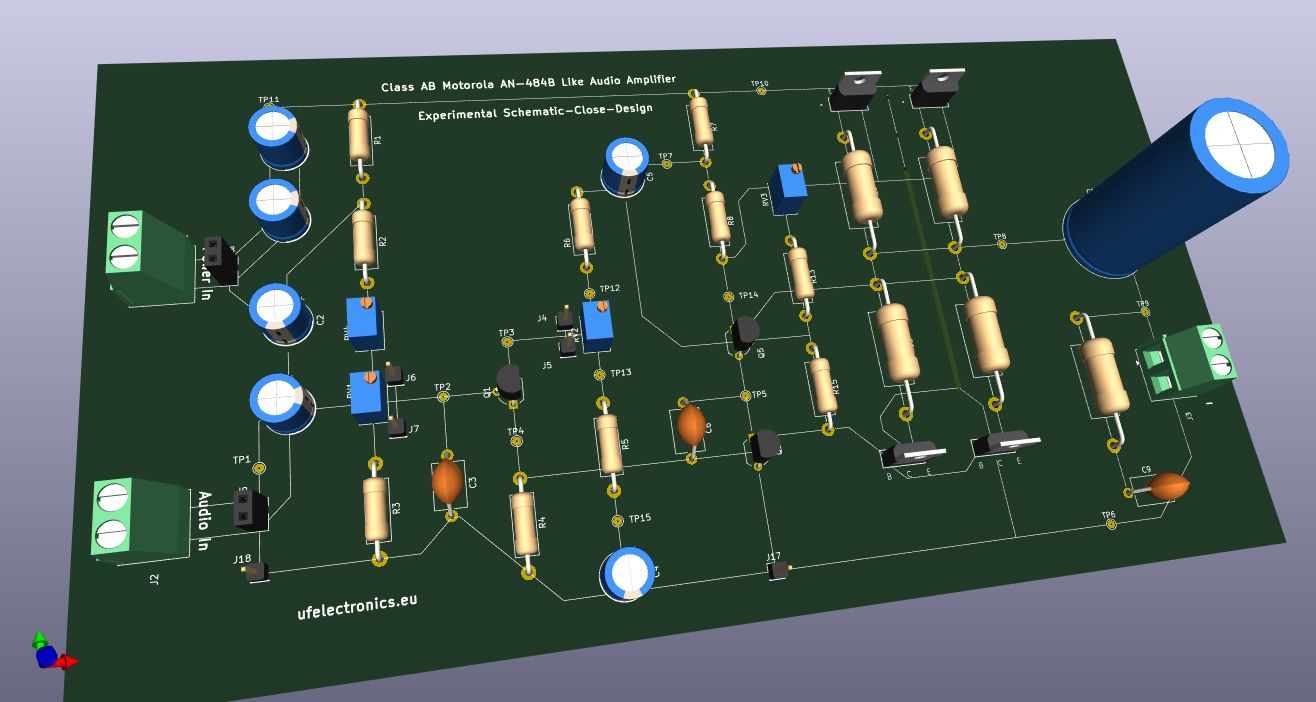
Motorola Class AB BJT Amplifier – Free PCB design Downloads
Build and experiment with the Motorola BJT Amp discussed on my LinkedIn profile back in November and December. Download the KiCad files for free from my Github repo: https://github.com/ufelectronics/classAB-motorola-PCB-layout If you missed it, I once shared the KiCad file for simulating the Motorola AN-484A transistor amplifier. Now I’m sharing the KiCad files for…
-
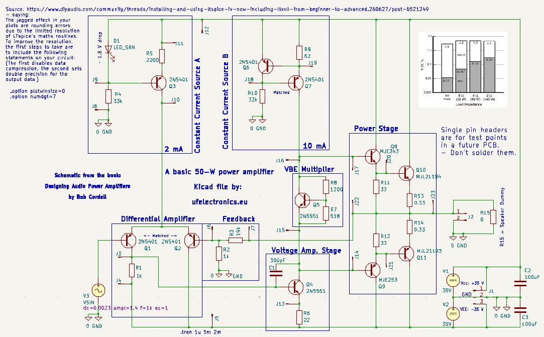
Free KiCad schematic for a 50W to 145W Audio Power Amplifier
This is a basic high power audio amplifier constructed by Bob Cordell. Understanding this audio power amplifier sets the ground for understanding high power, transistor based audio amplifiers. – That is my experience. In his book ‘Designing Audio Power Amplifiers’ you will find detailed explanations on how the various parts of it work. – Very…
-
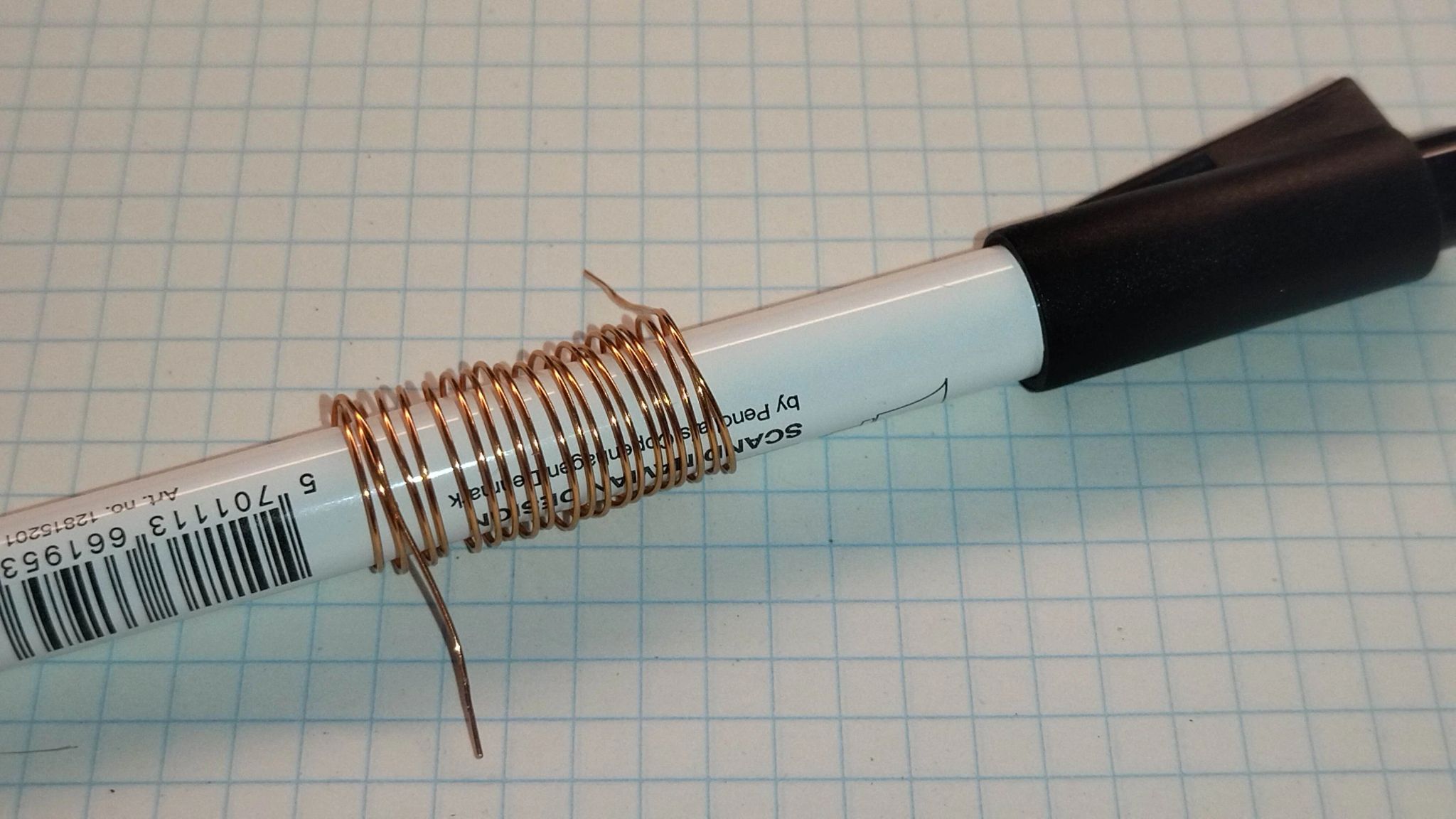
Uneven DIY coils for RF are a past
Winding them with bare copper wire: * They won’t get an even distributed spacing * Handling them, changes their inductance * They partly uncoil again, as you let go Nothing is controllable. Until you take duct tape, alias ‘Panzer-tape’, alias Gaffa and what else you call it. Take a random object with the desired diameter.…
-
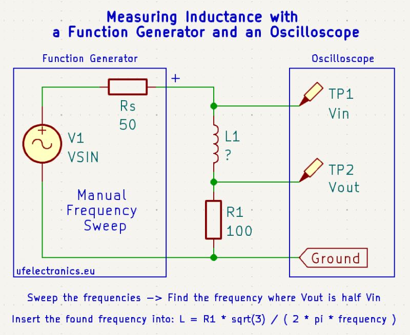
Measuring Inductance or Capacitance without an LCR-meter
You have a DIY inductor and no LCR-meter at hand? – No problem. A known resistor in series, and some calculations make the day. L = R * sqrt(3) / ( 2 * π * f ) Example Measurements: * R1 = 99.82 Ω * Vout = Vin / 2 at 901 khz ( 901,000 Hz…
-
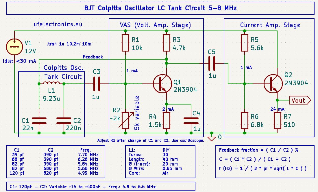
Free KiCad schematic for a BJT based LC Colpitts Oscillator, 5 – 8 MHz
This oscillator is based on two transistors. No crystals, by purpose. It can oscillate on various frequencies between 4.8 MHz and 8 MHz. With a variable capacitor (around 15 – 400 pF) instead of C2, you can dynamically vary the frequency in parts of that range. Its functionlity is verified by real world build and…
-
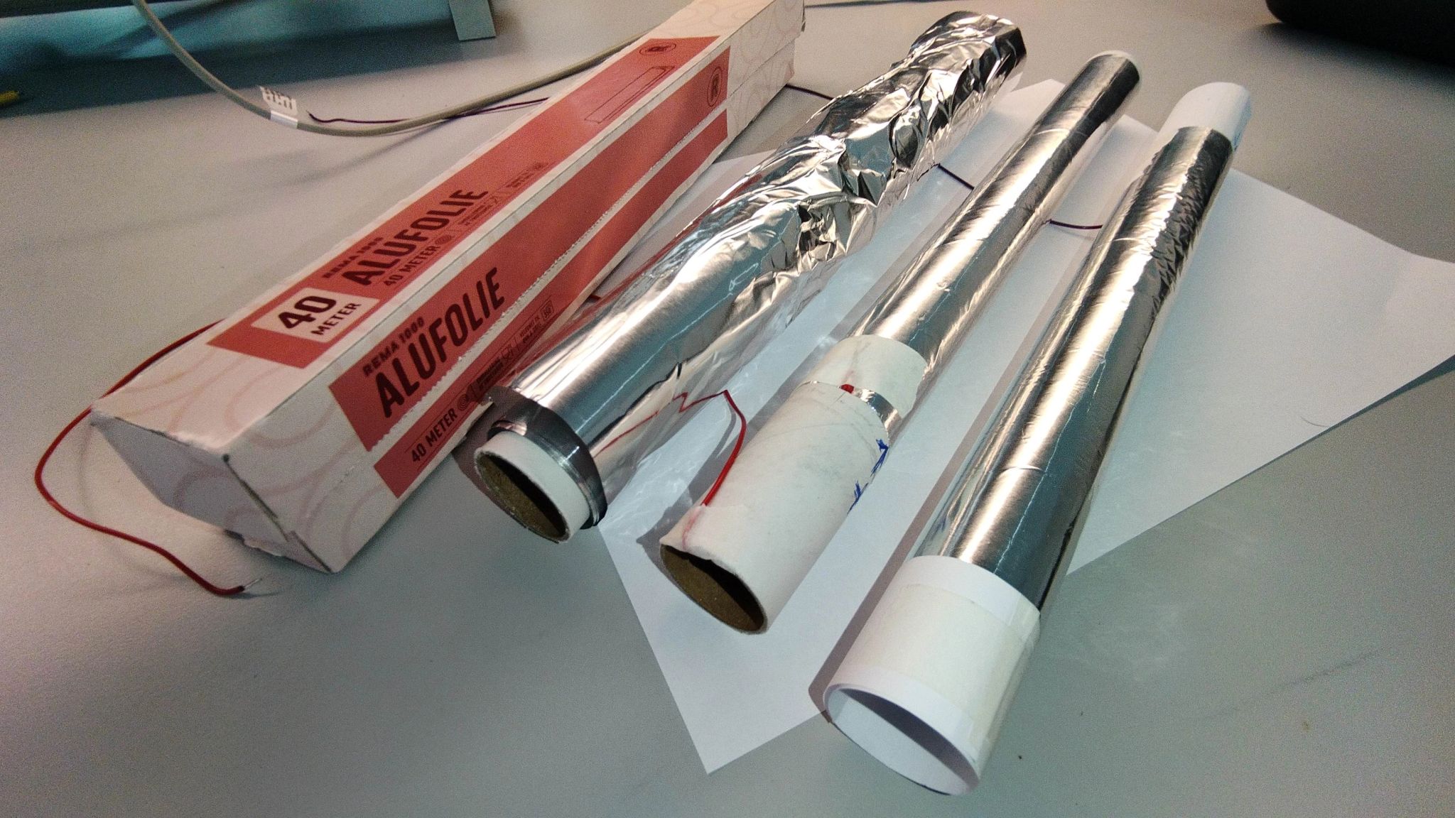
16 pF to 650 pF DIY variable capacitor
16 pF to 650 pF DIY variable capacitor from ordinary aluminium foil (alufoil), A4 paper and a cardboard tube from an empty alufoil package. Roll one round of alufoil on the blank cardboard tube. Fix it with tape. Leave 5 cm / 2 inch free from alufoil at one end. Roll a A4 paper around,…
-
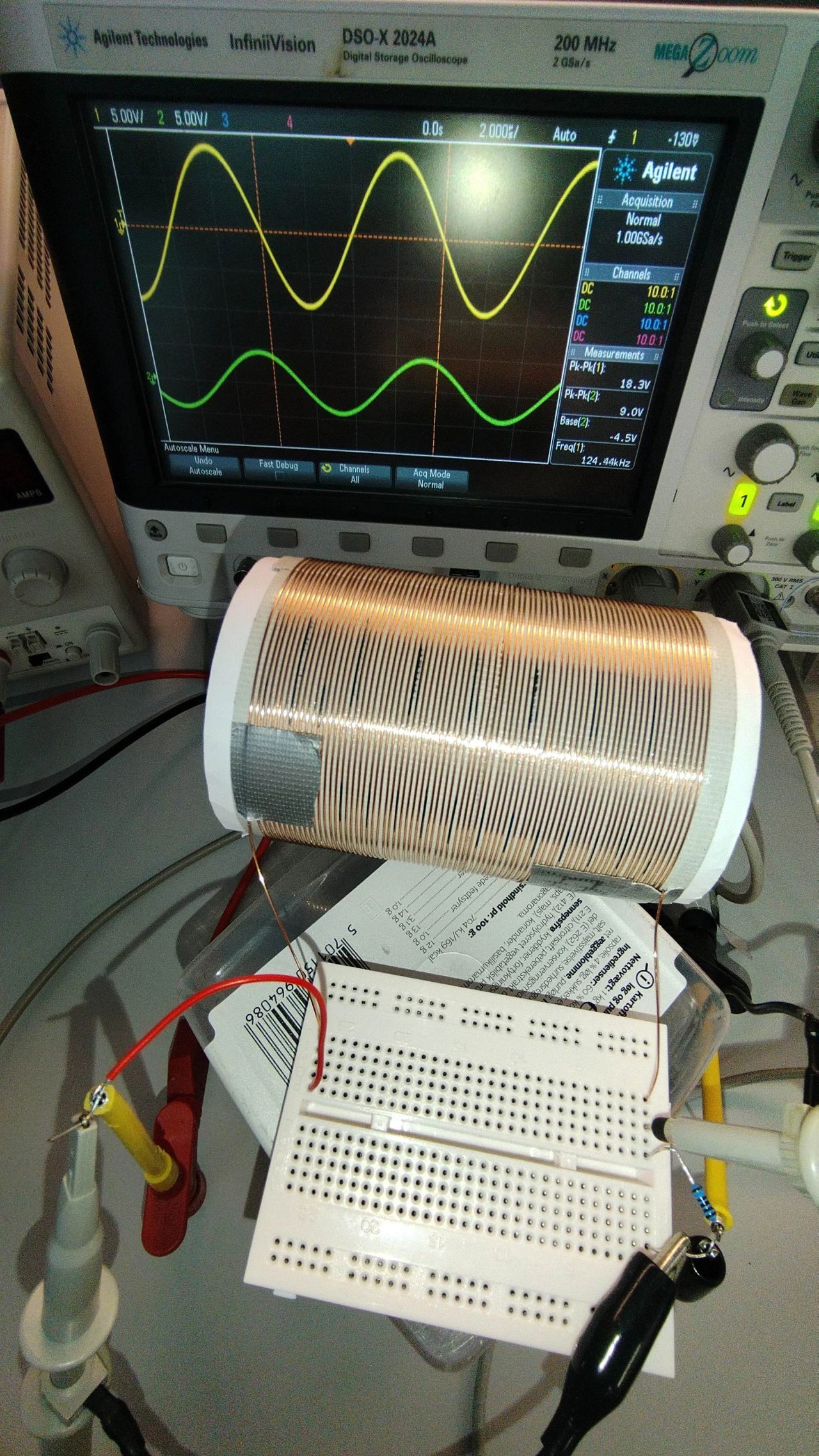
How to wind a perfect DIY inductor
Take something of a fitting diameter that is as smooth as the side of a full, unopened soda can. Wrap a double layer of printer paper on it. Once bent, for instance. Fix it with tape as a tube, but let it be just about slidable over the can. This layer is helpful in many…
-

DIY Single to Dual Power Supply from 5V – 15V, with Virtual Ground
DIY Single Rail to Double Rail with Virtual Ground / Rail Splitter / Voltage Divider Just released a video on how to create a small dual power supply based on a single power supply of between 5V an 15V. Schematic update 2028.03.03. NOTE: The pinout in the schematic does NOT represent the μA741C pinout. The…