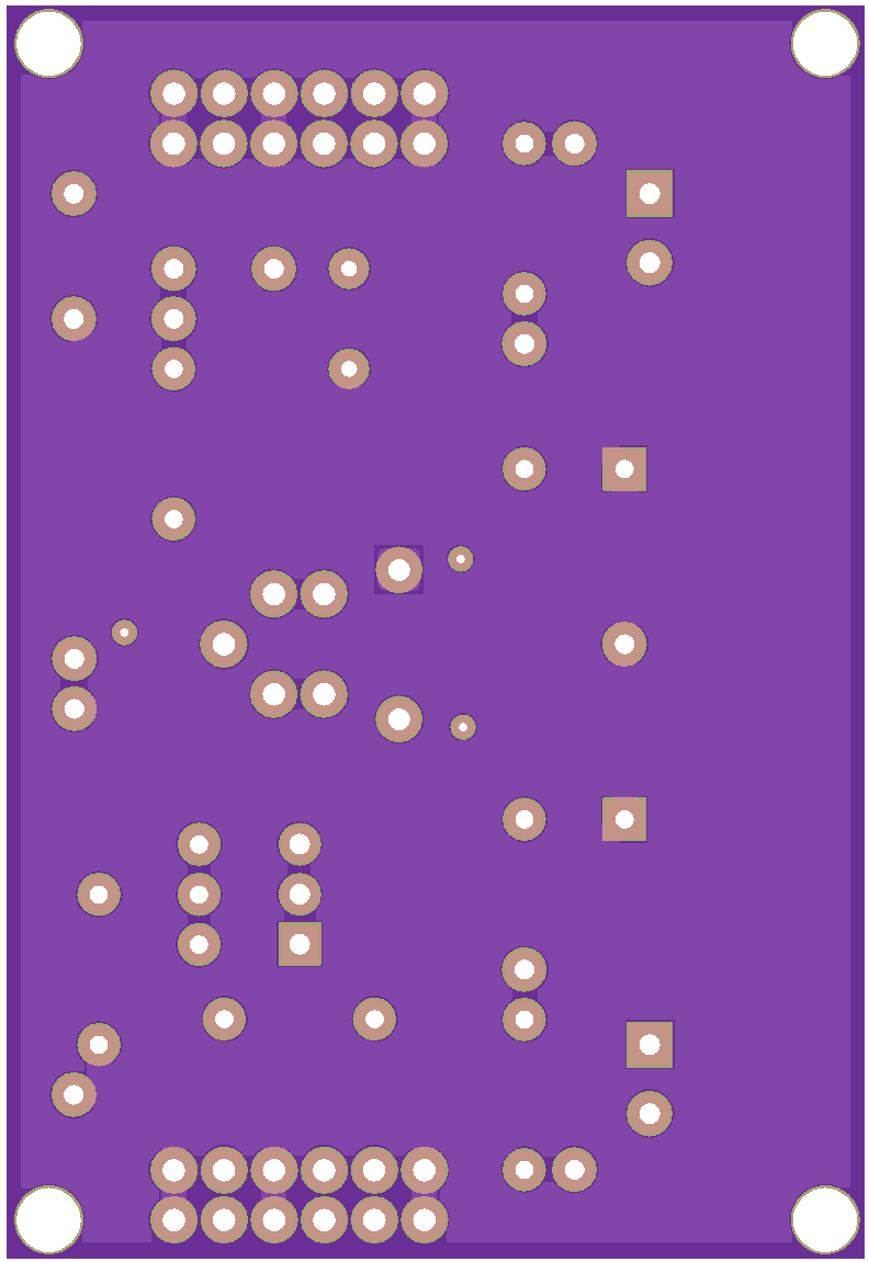
Description
A modular power stage for experimenting with power transistors
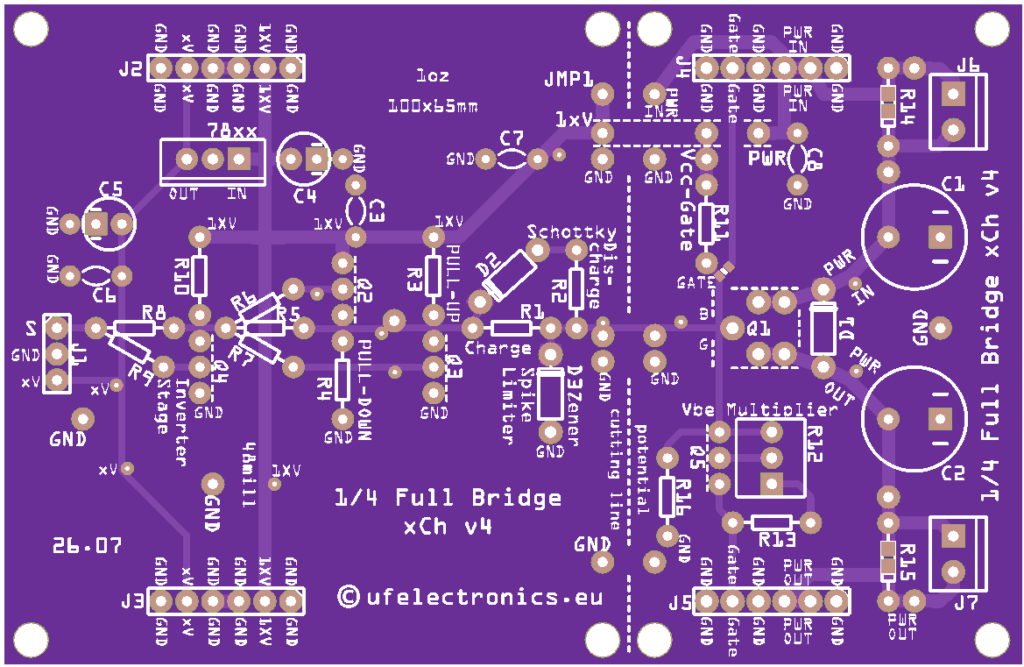
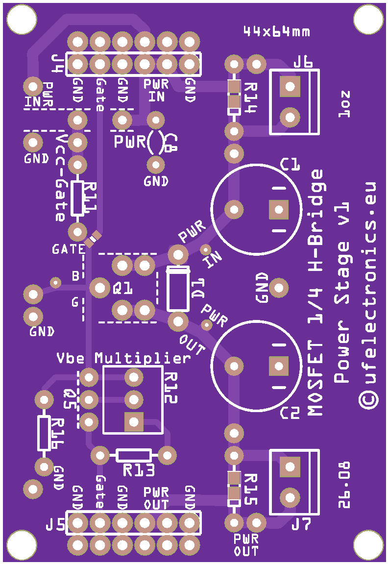
The 1/4 H-Bridge Power Stage is a compact, versatile power switching stage designed for experimentation with power transistors and switching circuits.
It represents one quarter of a conventional H-bridge and can be used as a building block for half-bridges, full H-bridges, buck converters, boost converters and other switching power circuits.
The board is deliberately kept focused on the power stage itself. The switching device is driven from an external signal or gate/base driver, allowing you to experiment with different driver circuits and control methods without having to redesign the power section.
Experiment. Change it. Measure it. Understand it.
What is a 1/4 H-Bridge?
A conventional H-bridge consists of four switching devices arranged around a load.
This board contains one quarter of that switching arrangement, making it possible to build larger switching circuits from individual building blocks.
Two boards can, for example, be combined to form a complete half-bridge, while four can be used to construct a full H-bridge.
The modular approach also makes the individual switching stages easier to study and measure.
More than just a MOSFET board
Although MOSFETs are a natural application for this type of power stage, the board is not limited to MOSFETs.
The power-transistor section is designed to accommodate suitable power transistor types, including the xx31/xx32 transistor variants used in experimentation with this board.
This makes the board useful for comparing different power-switching technologies and for studying the practical differences between their drive requirements and switching behaviour.
The actual choice of transistor is left to the experimenter.
Designed to work with an external driver
The 1/4 H-Bridge Power Stage does not attempt to combine the power stage and the driver into one board.
Instead, the switching device is controlled through external connections.
This makes it possible to use the same power stage with:
- A simple signal generator
- A microcontroller
- A dedicated gate driver
- The MOSFET Gate Driver Experimentation Board
- Other experimental driver circuits
This separation is particularly useful when learning how the driver and power stage interact.
You can change the driver without changing the power stage – or change the power transistor without redesigning the driver.
Typical applications
The board can be used as a building block for many different switching experiments:
Buck converter
Use the switching stage together with a suitable inductor, diode or synchronous switching arrangement and control signal to investigate step-down DC/DC conversion.
Boost converter
Configure the switching stage for step-up conversion and investigate the relationship between switching, inductance, duty cycle and output voltage.
Half-bridge
Combine two 1/4 H-Bridge Power Stage boards to create a complete half-bridge.
Full H-bridge
Four stages can be combined to create a complete H-bridge for applications such as motor control, polarity reversal and switched power conversion.
Power transistor experiments
Investigate switching behaviour, conduction losses, drive requirements, switching speed and the effect of different transistor types.
A building block for experimentation
The board is intentionally not a complete converter.
It provides the power switching stage, while the experimenter supplies the control signal, driver circuitry and external components required for the particular experiment.
This makes the board useful for teaching and experimentation because the complete system can be built up in stages:
Signal Source → Driver → Power Stage → Load
Each part can be changed, measured and studied independently.
Educational applications
The 1/4 H-Bridge Power Stage is particularly suited to electronics education where students need to move beyond theoretical switching circuits and work with an actual power stage.
Experiments can include:
- Switching a resistive load
- Investigating transistor switching losses
- Comparing power transistor types
- Measuring switching waveforms
- Investigating gate/base drive requirements
- Building a half-bridge
- Building a full H-bridge
- Constructing buck and boost converters
- Studying PWM control
- Investigating dead time and shoot-through
- Measuring voltage and current in switching circuits
The open nature of the board makes it possible to see and measure what is actually happening in the circuit rather than hiding the switching stage inside an integrated converter.
Combine it with the MOSFET Gate Driver Experimentation Board
The MOSFET Gate Driver Experimentation Board can be used as the driver side of the experiment, while the 1/4 H-Bridge Power Stage provides the power switching stage.
This creates a modular experimental platform where the relationship between the driver and the power transistor can be explored directly.
For example:
PWM Source → Gate Driver → 1/4 H-Bridge Power Stage → Load
The boards can also be used independently with other signal sources and driver circuits.
Why a separate power stage?
In many commercial power-converter modules, the controller, driver and power transistors are integrated into a single circuit.
That is convenient when building a finished product, but it makes experimentation much more difficult.
With separate boards, you can change one part at a time.
Try a different driver.
Try a different switching transistor.
Change the PWM frequency.
Change the duty cycle.
Measure the gate or base signal.
Look at the switching node.
Measure the current.
Then change something and see what happens.
That is the purpose of the board.
Features
- 1/4 H-bridge power-stage configuration
- Suitable for power-transistor experimentation
- Supports suitable MOSFET and other power-transistor types
- Designed for use with an external driver
- Suitable for building half-bridges and full H-bridges
- Suitable as a switching stage for buck and boost converter experiments
- Exposed test and connection points for experimentation
- Modular design
- Designed for education, prototyping and hands-on experimentation
Important
This is an experimental power-stage PCB, not a complete power converter or motor controller.
The board does not include a PWM controller or a dedicated gate/base driver. An appropriate external driver and suitable power components must be selected for the intended application.
The maximum voltage, current and switching frequency depend on the transistor used, the external circuitry, PCB configuration, cooling and the particular application.
Always verify the ratings and operating conditions of the components before applying power.
What’s included?
2 × 1/4 H-Bridge Power Stage PCB
Components are not included unless specifically stated.
The board is supplied as a bare PCB for experimentation and assembly.