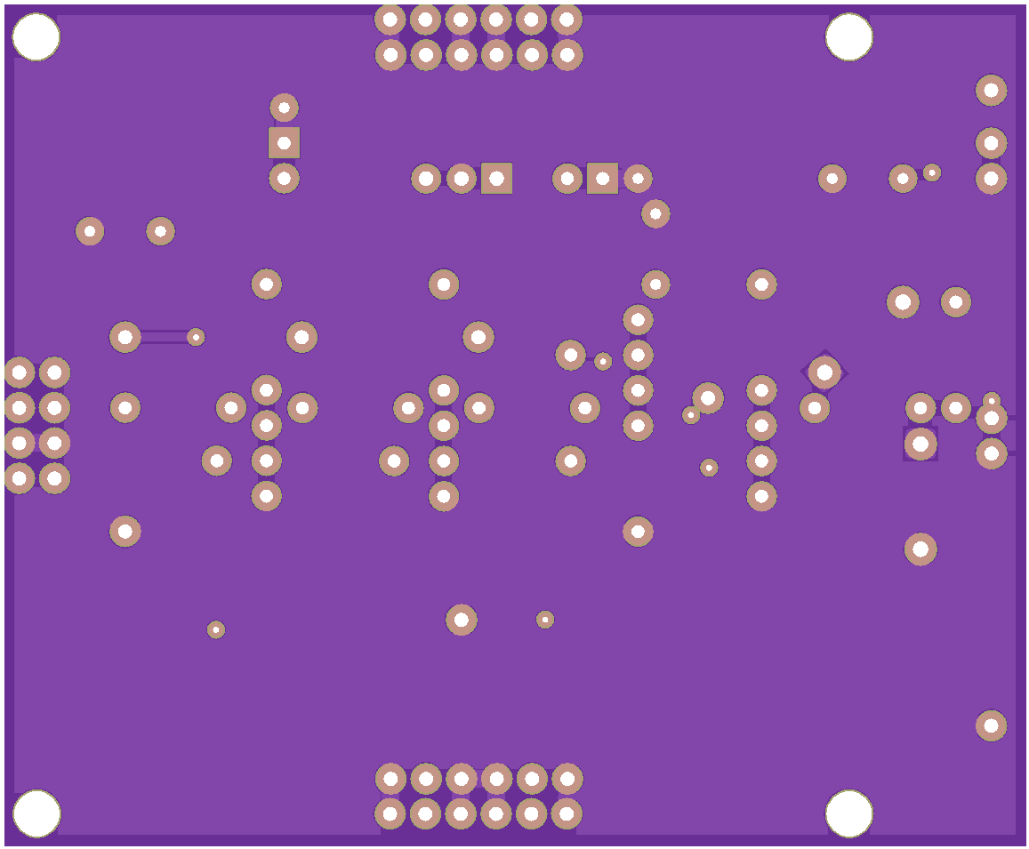
Description
Learn how to drive a power MOSFET
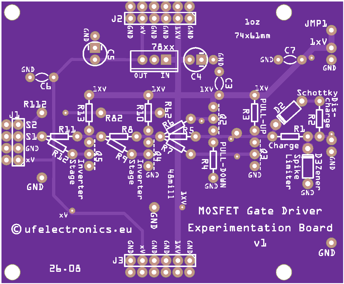
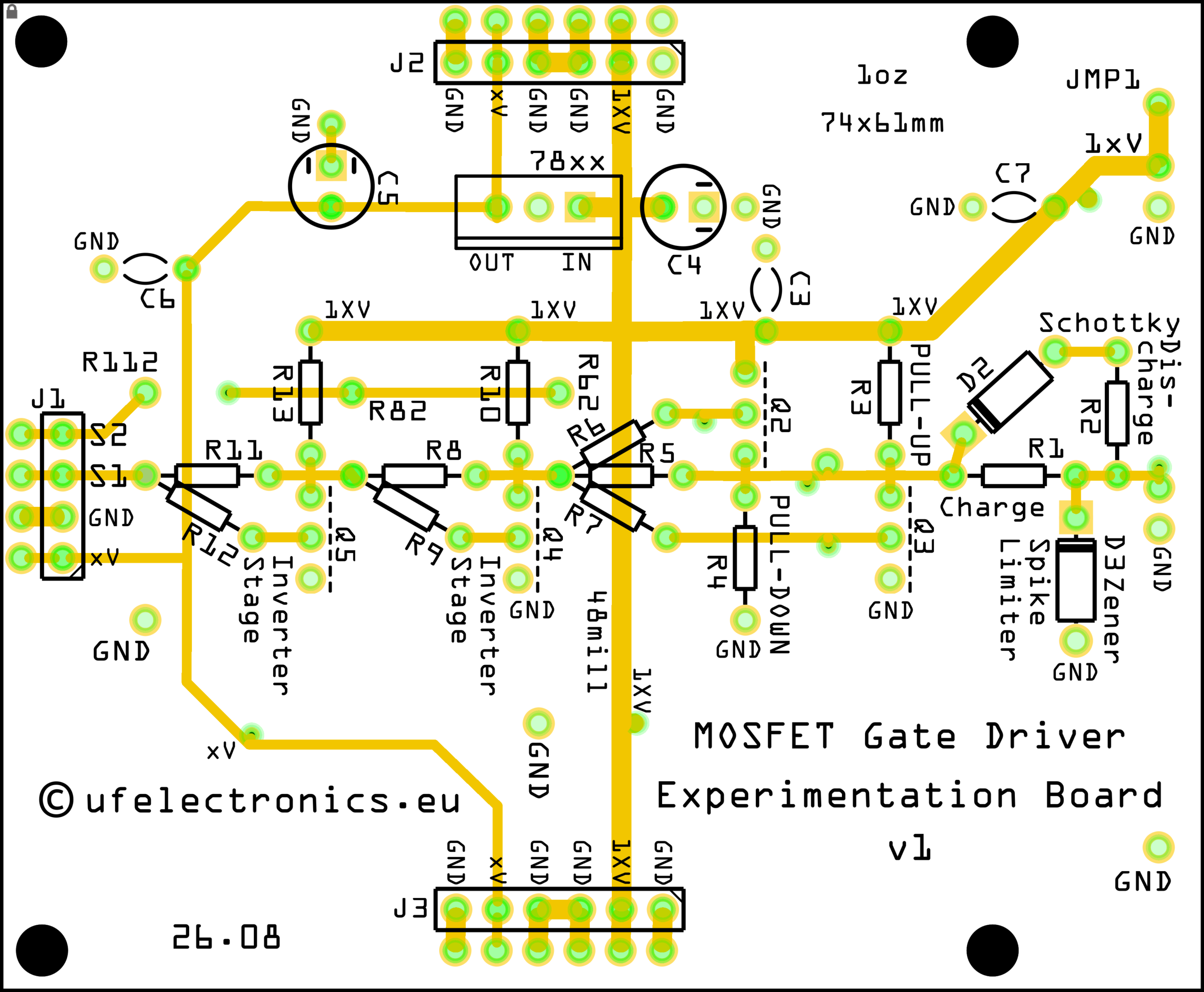
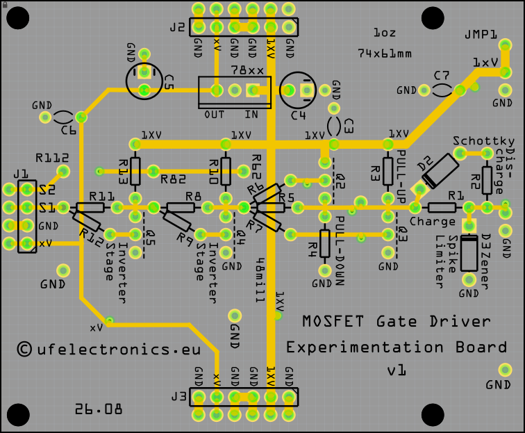
The MOSFET Gate Driver Experimentation Board v1 is an educational development board for learning the fundamentals of driving power MOSFETs.
Instead of hiding the gate-driver circuitry inside a dedicated driver IC, this board uses discrete transistors, allowing you to see, measure and experiment with the individual stages of the driver.
A power MOSFET may be voltage-controlled, but its gate still has to be charged and discharged when the device switches. The gate driver provides the current needed to do this quickly and reliably.
This makes the board an ideal companion for studying the relationship between a control signal, a gate driver and a power switching device.
From control signal to power MOSFET
A microcontroller, signal generator or other logic circuit can provide the control signal, but it may not be the best source for directly driving a power MOSFET.
The gate of a power MOSFET behaves like a capacitive load. Every time the MOSFET switches, the gate must be charged and discharged. The required gate charge, drive current and switching speed therefore become important considerations.
The Gate Driver Experimentation Board provides the intermediate stage:
Control Signal → Gate Driver → Power MOSFET
This lets you investigate what happens at each stage of the signal path.
Why use a discrete gate driver?
Modern power electronics often uses dedicated gate-driver ICs because they provide high drive currents and sophisticated features in a compact package.
But an integrated driver can hide much of what is actually happening.
With a discrete transistor driver, you can examine the circuit itself.
You can:
- Follow the control signal through the driver
- Measure the driver output
- Observe the MOSFET gate waveform
- Investigate turn-on and turn-off behaviour
- Experiment with gate resistance
- Compare different power MOSFETs
- Investigate the effect of MOSFET gate charge
- Study switching speed and switching losses
The board is therefore intended as an experimentation platform rather than a black-box solution.
Learn by measuring
Connect a signal source and observe the driver output with an oscilloscope.
Then change something.
Try a different MOSFET.
Change the gate resistor.
Change the switching frequency.
Change the control signal.
Measure the gate voltage.
Observe the rise and fall times.
Look at what happens when the MOSFET gate has to be charged and discharged.
These experiments make the otherwise abstract concepts of gate charge, drive current and switching time much easier to understand.
Gate charge matters
A power MOSFET does not simply turn on instantaneously when a voltage is applied to its gate.
The driver has to supply charge to the gate, and the speed at which this happens depends on both the MOSFET and the driver.
The total gate charge (Q_G), gate-drive voltage and switching frequency all influence the energy required to drive the MOSFET.
This gives you a practical way to investigate questions such as:
What happens when I use a MOSFET with a larger gate charge?
What happens when I increase the gate resistance?
How much drive current is required?
How does switching frequency affect the driver?
These are exactly the kinds of questions that become interesting when working with real power electronics.
Designed for power MOSFETs
The board is intended for experimentation with power MOSFETs.
The MOSFET is mounted as a separate power device, allowing you to change the device and investigate how different MOSFET characteristics affect the gate-drive circuit.
This makes the board particularly useful when comparing datasheet parameters such as:
- Gate threshold voltage
- Total gate charge
- Input capacitance
- Drain-source voltage rating
- On-state resistance
- Switching characteristics
The important point is that the gate driver and the power MOSFET can be studied as two separate parts of the system.
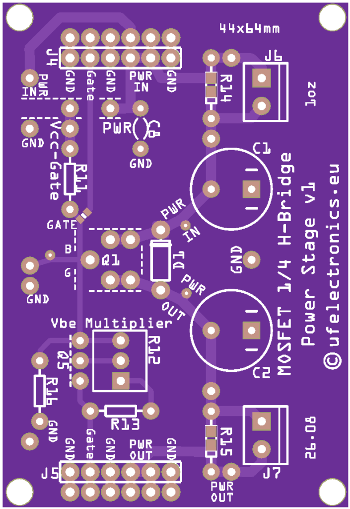
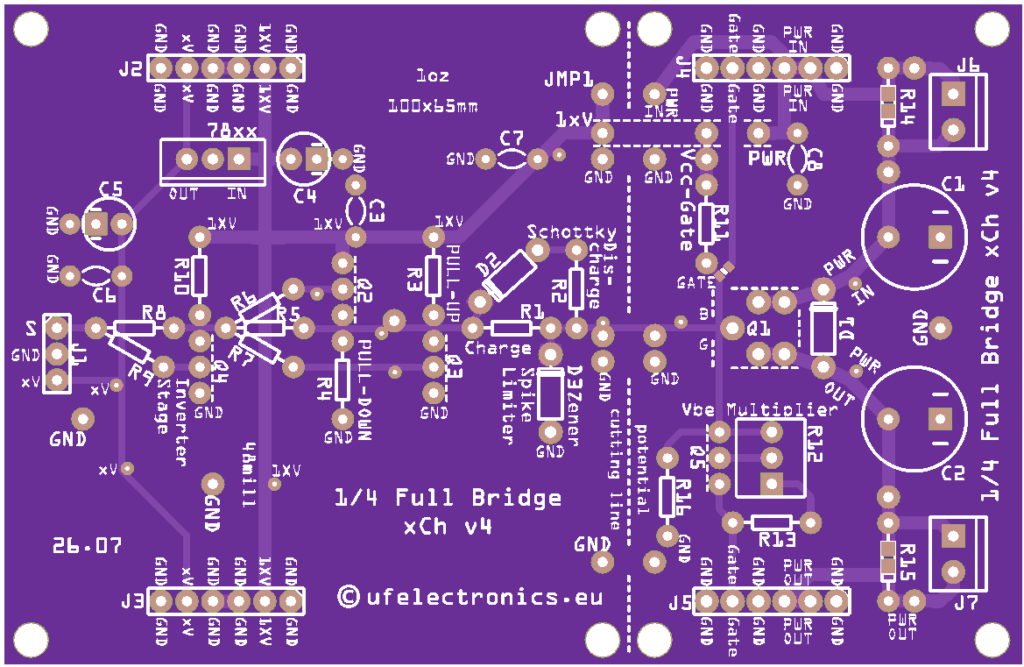
A companion to the 1/4 H-Bridge Power Stage
The MOSFET Gate Driver Experimentation Board and the 1/4 H-Bridge Power Stage are designed as complementary experimentation boards.
The Gate Driver board handles the control side.
The 1/4 H-Bridge Power Stage provides the power switching stage.
Together they create a modular experimental system:
PWM / Signal Source → Gate Driver → 1/4 H-Bridge Power Stage → Load
The two boards can also be used independently.
This separation makes it possible to experiment with the driver without immediately having to work with a high-power switching circuit – and later connect the driver to a real power stage when you are ready.
Educational applications
The board can be used for practical exercises in:
- MOSFET gate driving
- Power electronics
- PWM switching
- Gate charge
- Switching speed
- Gate resistance
- Turn-on and turn-off behaviour
- Power MOSFET selection
- Oscilloscope measurements
- Driver current requirements
- Switching losses
- Power-stage control
It is particularly suited to electronics students, educators, tutors and experimenters who want to understand the circuitry behind power switching rather than simply use a finished driver IC.
Suggested experiments
1. Drive a MOSFET from a signal generator
Apply a square-wave signal and observe the driver output and MOSFET gate voltage.
2. Change the gate resistor
Investigate how the gate resistance affects the charging and discharging of the MOSFET gate.
3. Compare MOSFETs
Use different power MOSFETs and observe how their gate characteristics influence switching behaviour.
4. Change the switching frequency
Observe how increasing the switching frequency affects the driver and the power MOSFET.
5. Examine turn-on and turn-off
Use an oscilloscope to investigate the difference between the rising and falling edges of the gate signal.
6. Connect a power stage
Once the gate-drive behaviour is understood, connect the board to a 1/4 H-Bridge Power Stage and investigate the complete switching path.
Built for experimentation
The board is not intended to hide the complexity of MOSFET gate driving.
It is intended to expose it.
That means the board is useful both when something works exactly as expected – and when it doesn’t.
Change it. Measure it. Find out why.
That is where the learning happens.
Features
- Designed for learning MOSFET gate-drive fundamentals
- Discrete transistor gate-driver circuit
- Intended for power MOSFETs
- External control-signal input
- External connection to the MOSFET power stage
- Suitable for oscilloscope-based measurements
- Useful for investigating gate charge and switching behaviour
- Suitable for experimenting with gate resistance and switching frequency
- Modular design
- Ideal companion to the 1/4 H-Bridge Power Stage
- Designed for education, experimentation and hands-on learning
Important
This is an experimental MOSFET gate-driver PCB, not a complete power converter or motor controller.
The board is intended to be used with a suitable power MOSFET and appropriate external circuitry.
The achievable switching speed, gate-drive voltage and operating conditions depend on the selected MOSFET, component values, supply voltage, layout and external circuit.
Always check the ratings of the MOSFET and all other components before applying power.
What’s included?
2 × MOSFET Gate Driver Experimentation Board v1 PCB
Components are not included unless specifically stated.
The board is supplied as a bare PCB for experimentation and assembly.