
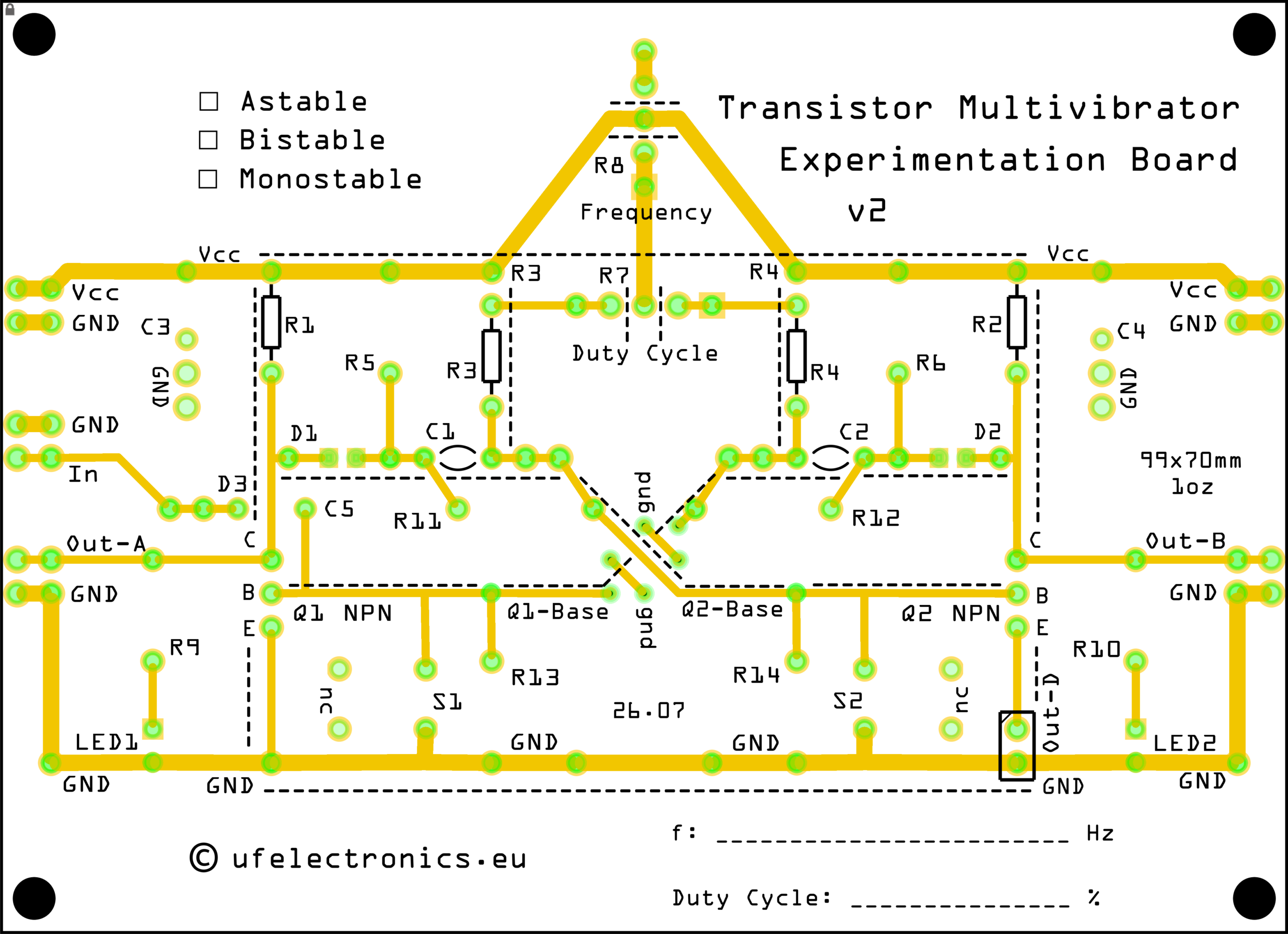
Designed for the Transistor Multivibrator Experimentation Board, this circuit is a great introduction to transistor-based oscillators and multivibrator operation.
BOM (Bill of materials)
C1, C2: 100 nF (2x)
JP1, JP2, Out-D1: Bridged (1x/3x)
Q1, Q2: 2N3904 (2x)
R1, R2: 2.2 kΩ (2x)
R3, R4: 33 kΩ (2x)
Version 2 of the PCB is coming this autumn and includes:
* Breadboard-friendly input and output pin header footprints
* Less visual clutter for beginners
* Improved labeling
See the downloadable schematics and BOM: