
Category: Builds
-
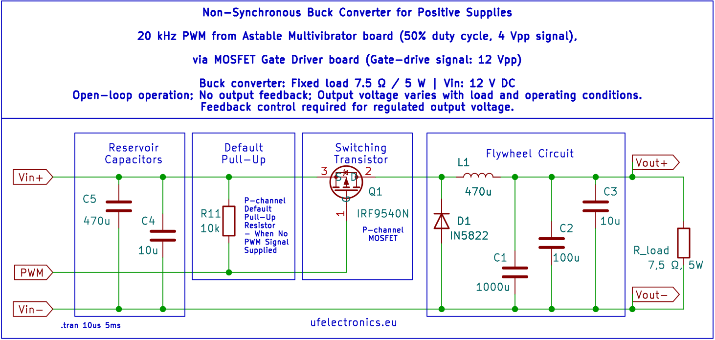
The Simple DIY Discrete Buck Converter Is Working: 80% Efficiency!
– Built with discrete components by design (no ICs), and deliberately kept simple to make it suitable for DIY. – It is a simple, open-loop, non-synchronous buck converter. It uses a 20 kHz, 50% duty-cycle astable multivibrator as the PWM signal source, a discrete transistor push-pull gate driver and a P-channel as the high-side switch.…
-
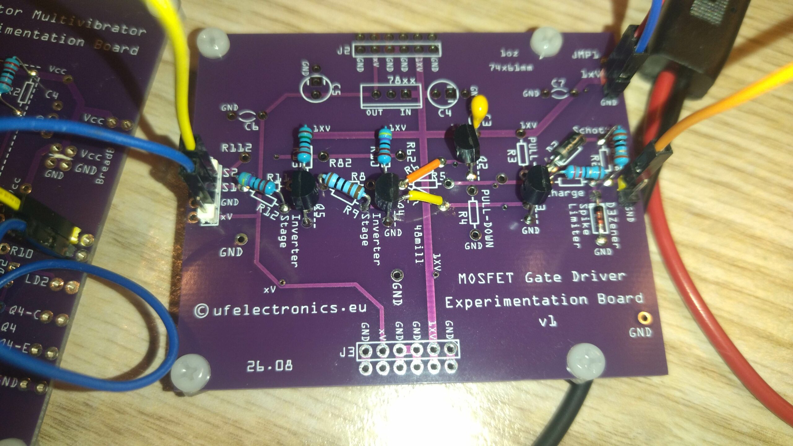
Understand MOSFET gate driving by building one with transistors
Investigating how basic components work is my guiding principle in this part of the DIY buck converter project, too. The circuit is built around a push-pull output stage, with several refinements and some essential supporting components. * Q2 and Q3 – Push-pull stage: Q2 sources current to charge the MOSFET gate; Q3 sinks current to…
-
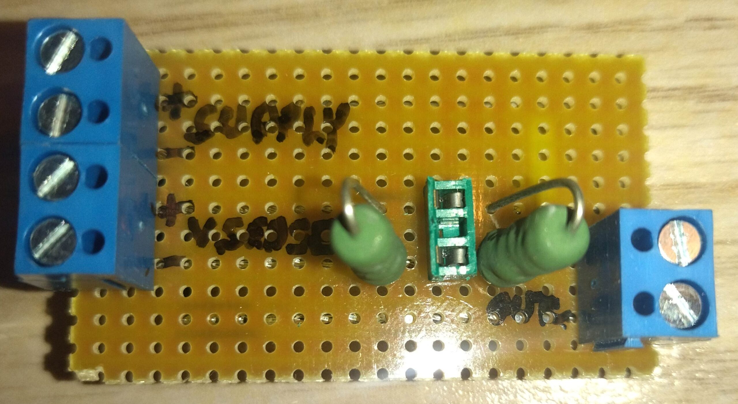
DIY shunt resistor for current measurement – how accurate is it?
I needed a shunt to measure current, but only had two 0.082 Ω, 3W resistors. Luckily, I found them in a scrapped PSU. Two resistors in parallel: 0.082 Ω || 0.082 Ω = 0.041 Ω, 6W total But how accurate is the result? And does it matter if the voltmeter connects through sense terminals about…
-
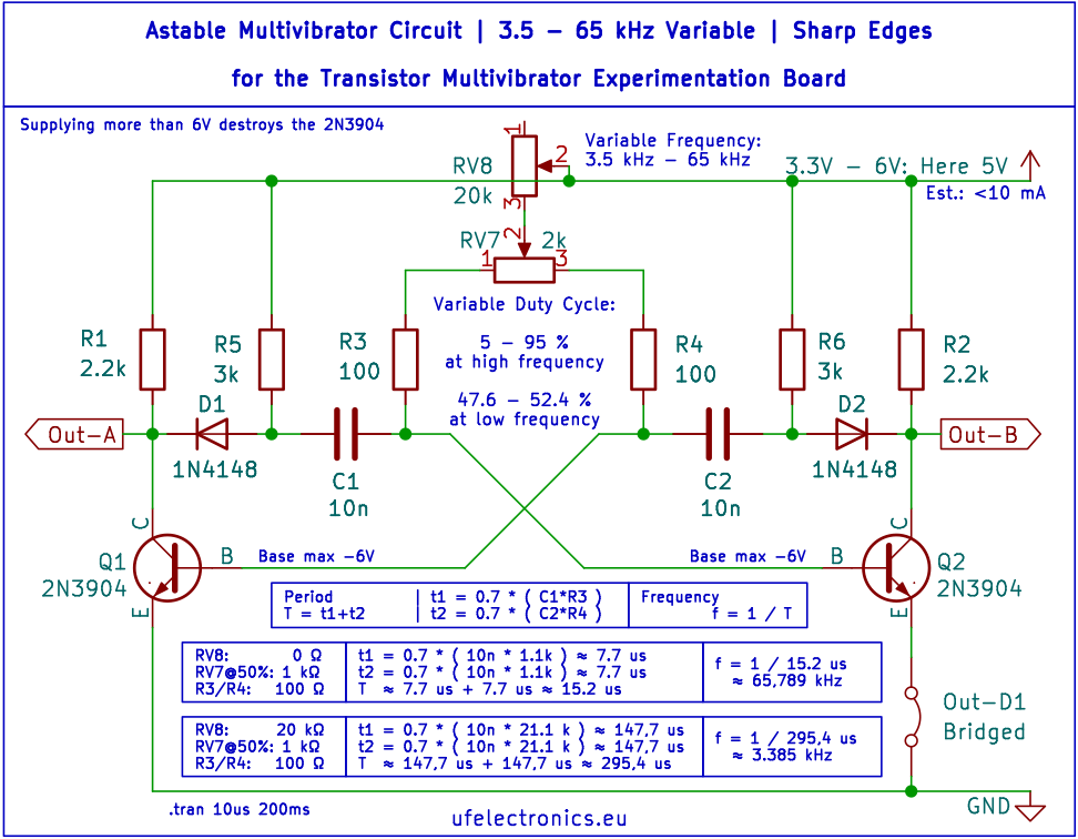
No signal generator? – Build a variable astable multivibrator
This one is intended to provide the ~20 kHz switching signal for our future buck converter. The AMV (astable multivibrator) gives us the signal, but we’re not quite ready to drive the MOSFET yet. We still need a gate driver between the AMV and the MOSFET to turn the 6 V logic-level signal into a…
-
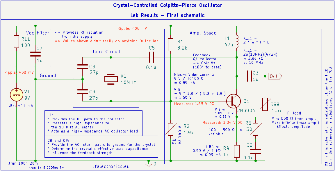
10 MHz Crystal Oscillator – Schematic and Build
The circuit has been built and tested on the bench. Below are some measurements from testing different component values and operating conditions. R5 – Emitter Resistor R5 = 30 Ω 4.74 Vpp 5.90 V min 10.64 V max R5 = 200 Ω 2.17 Vpp 7.63 V min 9.80 V max Interestingly, the lower-amplitude waveform looks…
-
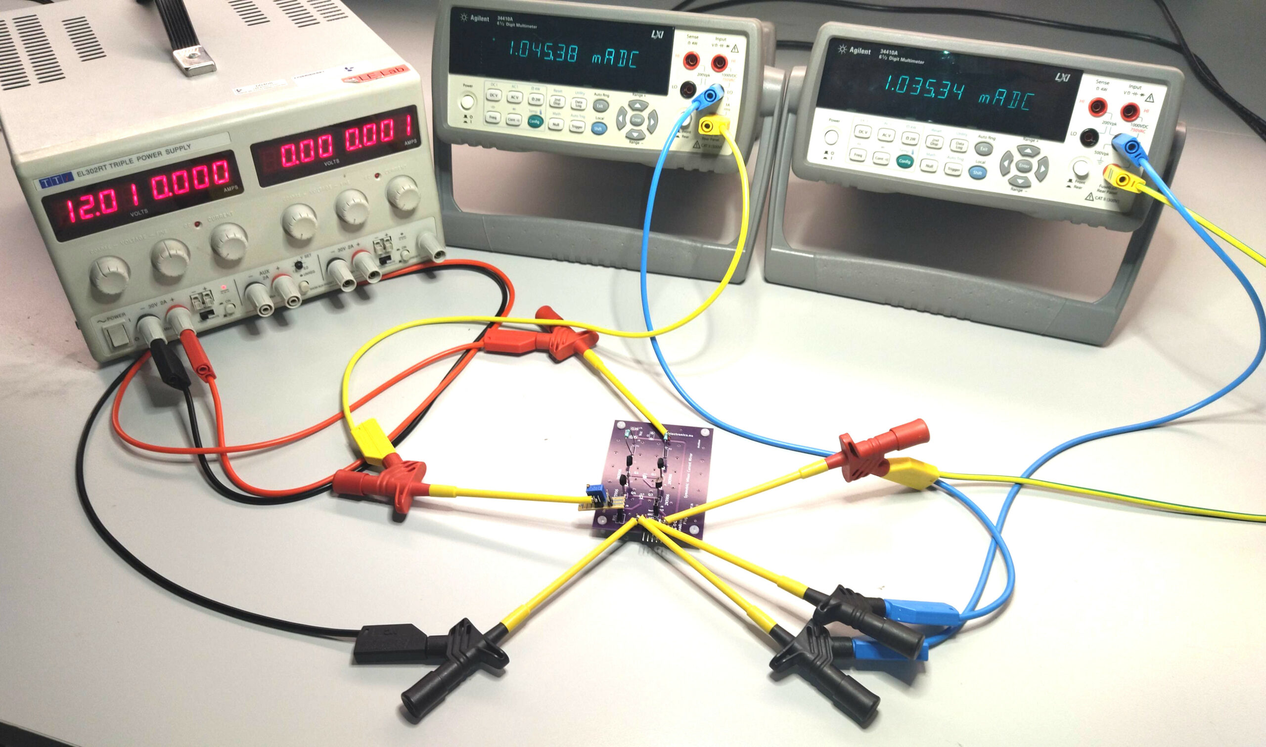
How well can a current mirror made from ordinary discrete transistors perform?…
– Only 11 µA difference between the reference current and the output current – – that is what I measured with a symmetric Wilson current source mirror built from ordinary, unmatched 2N3906 PNP transistors. For the experiment, I used: * 4 randomly selected 2N3906 PNP transistors * 2 randomly selected 18 Ω resistors * Both…
-
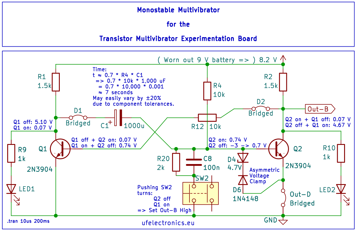
BJT Monostable Multivibrator – Schematic and Build
– and a Design Detail You Might Have Missed – When the trigger pulls the base of the second transistor low, the first transistor switches on and its collector falls rapidly from nearly Vcc to almost 0 V. BUT: The timing capacitor between the collector of Q1 and the base of Q2 cannot change its…
-
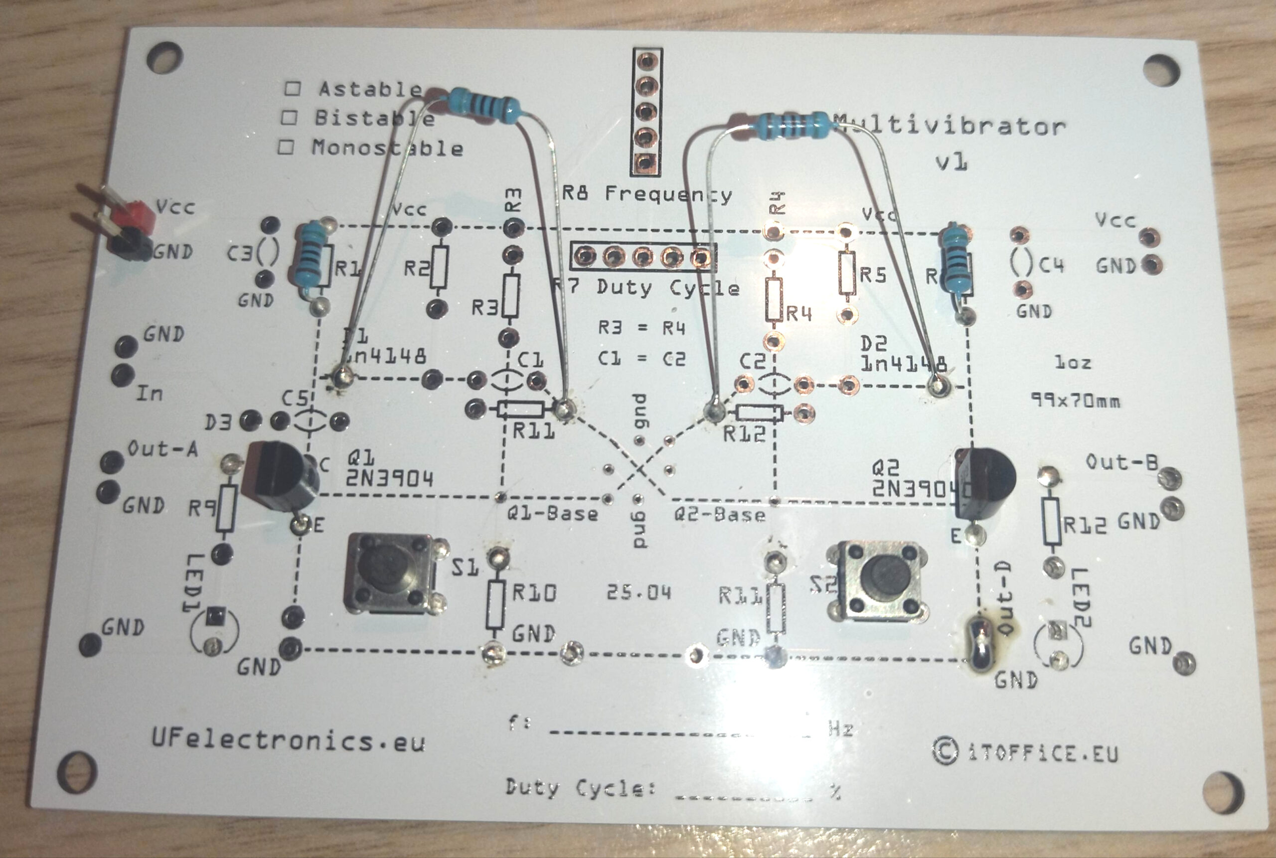
Triggered Bistable Multivibrator – Schematic and Build
PDF for downloading
-
Schematic for a Simple 218 Hz Astable Multivibrator
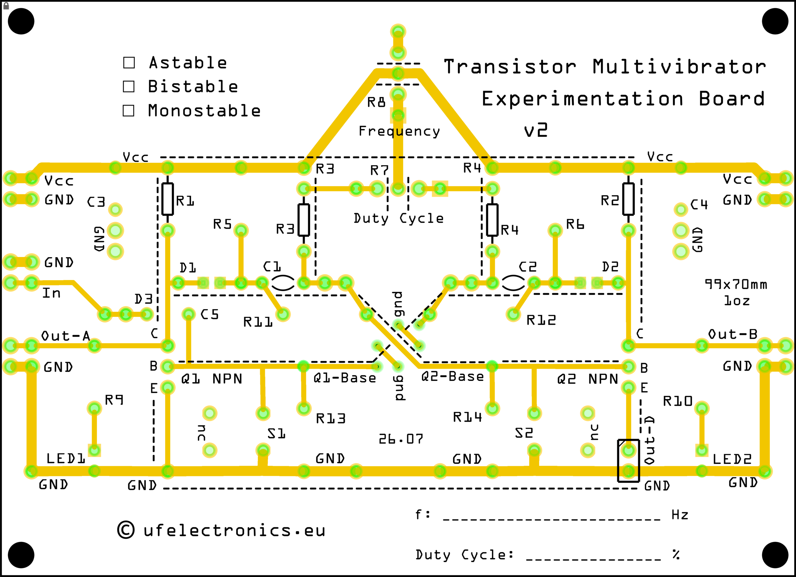
Designed for the Transistor Multivibrator Experimentation Board, this circuit is a great introduction to transistor-based oscillators and multivibrator operation. BOM (Bill of materials) C1, C2: 100 nF (2x) JP1, JP2, Out-D1: Bridged (1x/3x) Q1, Q2: 2N3904 (2x) R1, R2: 2.2 kΩ (2x) R3, R4: 33 kΩ (2x) Version 2 of the PCB is coming this…
-
Testing v8.1 of the BJT Transistor Experimentation Board…
…with a Colpitts oscillator setup. – See the schematics in the images. Version 8.1 adds: * Optional Vcc+ supply filter using resistor, ferrite bead or inductor * Collector resistor split for gain boost experiments * Additional feedback network for common collector stages * Extra ground point for cleaner external feedback wiring Everything worked as expected.…