– and a Design Detail You Might Have Missed –
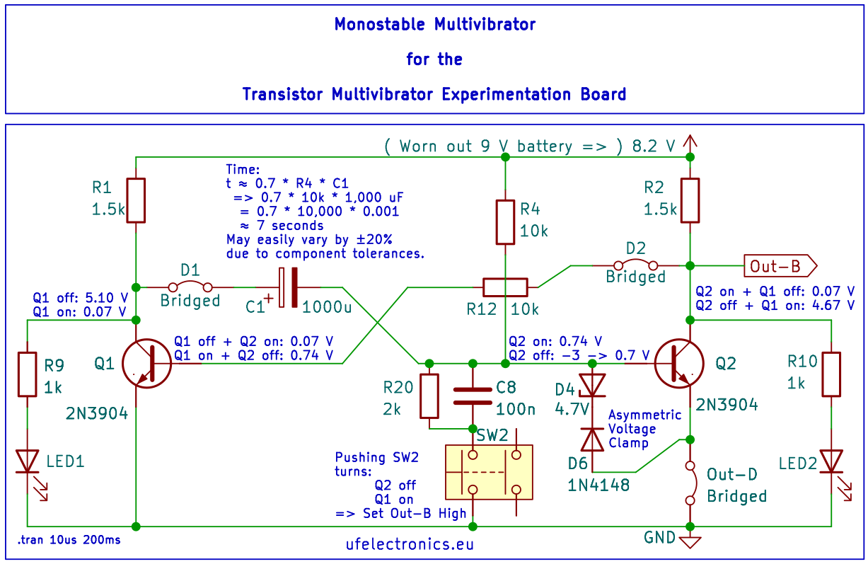
When the trigger pulls the base of the second transistor low, the first transistor switches on and its collector falls rapidly from nearly Vcc to almost 0 V.
BUT: The timing capacitor between the collector of Q1 and the base of Q2 cannot change its voltage instantaneously. Instead, it preserves its voltage, causing the base of Q2 to attempt to go several volts below ground.
– For a 2N3904, that can be a problem. The transistor’s maximum reverse base-emitter voltage (V_EBO-max) is only 6 V.
A common solution is to add a 1N4148 across the base-emitter junction.
base <-(1N4148) – emitter
That protects the transistor by clamping the base to about −0.7 V.
But there’s a catch…
By clamping the base so close to ground, you also reduce the available voltage swing of the timing capacitor. The result is a shorter timing interval than intended.
An improved solution:
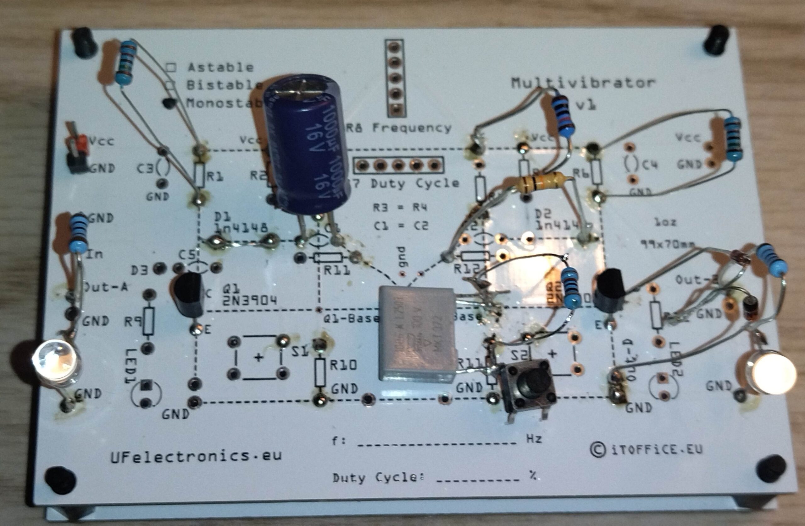
Use an asymmetric voltage clamp consisting of a 4.7 V zener diode in series with a 1N4148.
base – (zener)-> <-(1N4148) – emitter
Now the base can fall to approximately:
−(4.7 V + 0.7 V) ≈ −5.4 V
This provides three advantages:
* Protects the 2N3904 from excessive reverse base-emitter voltage.
* Preserves much more of the timing capacitor’s voltage swing.
* Provides a safer margin when operating from a 9 V supply.