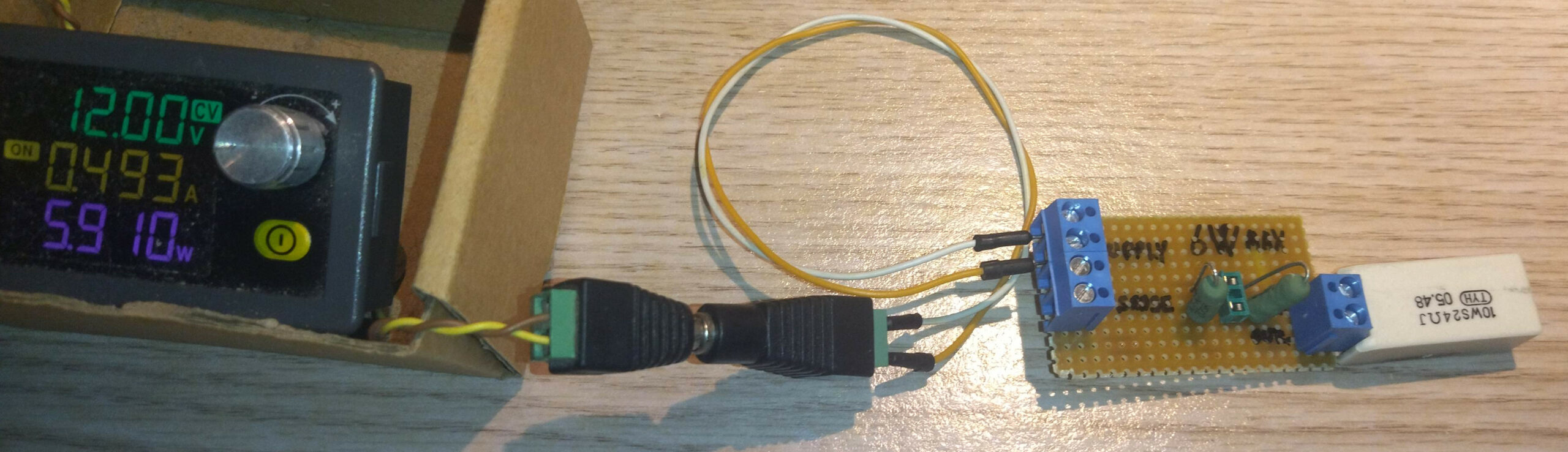
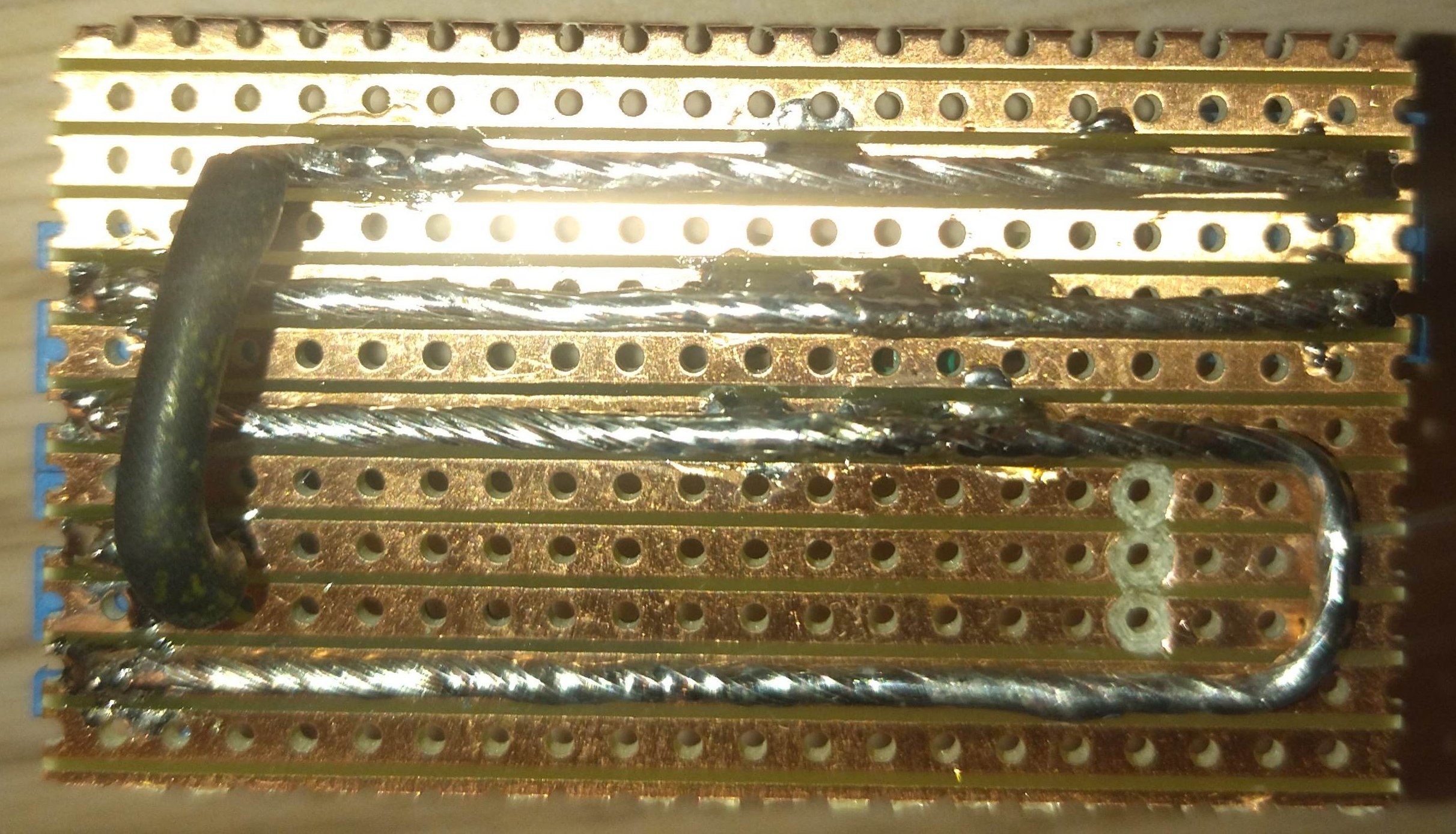
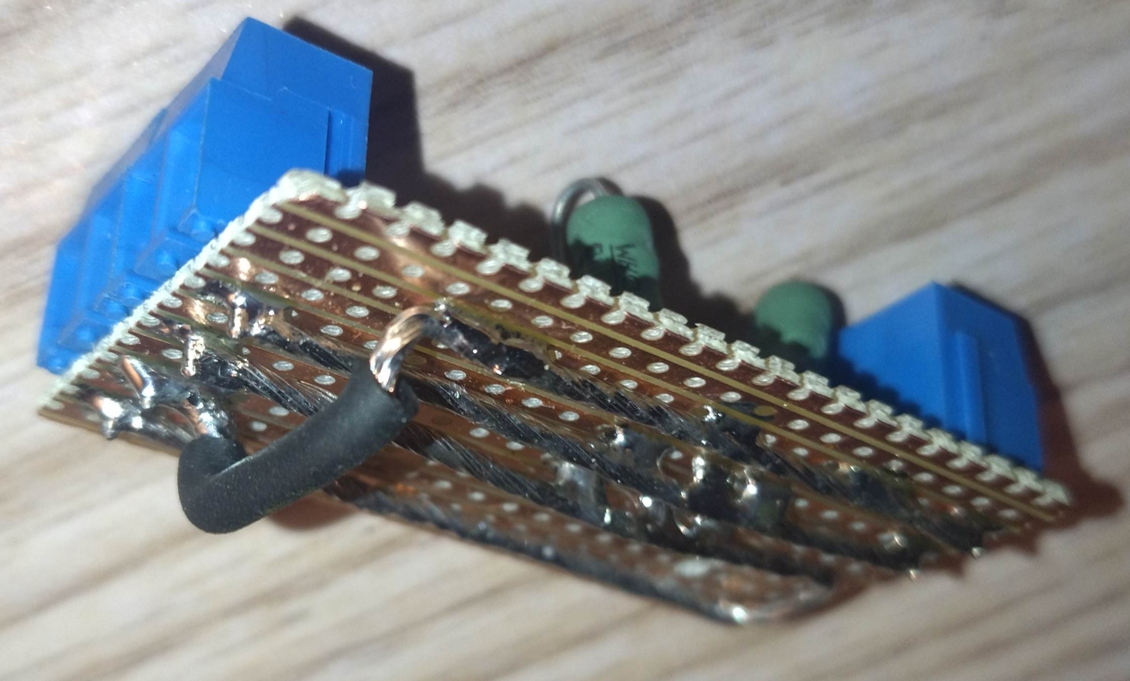
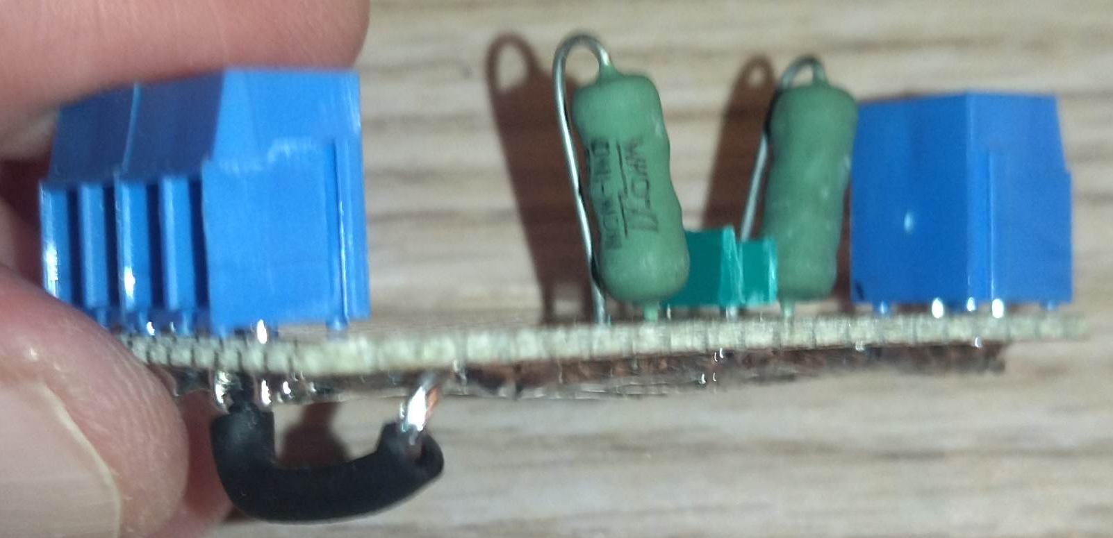
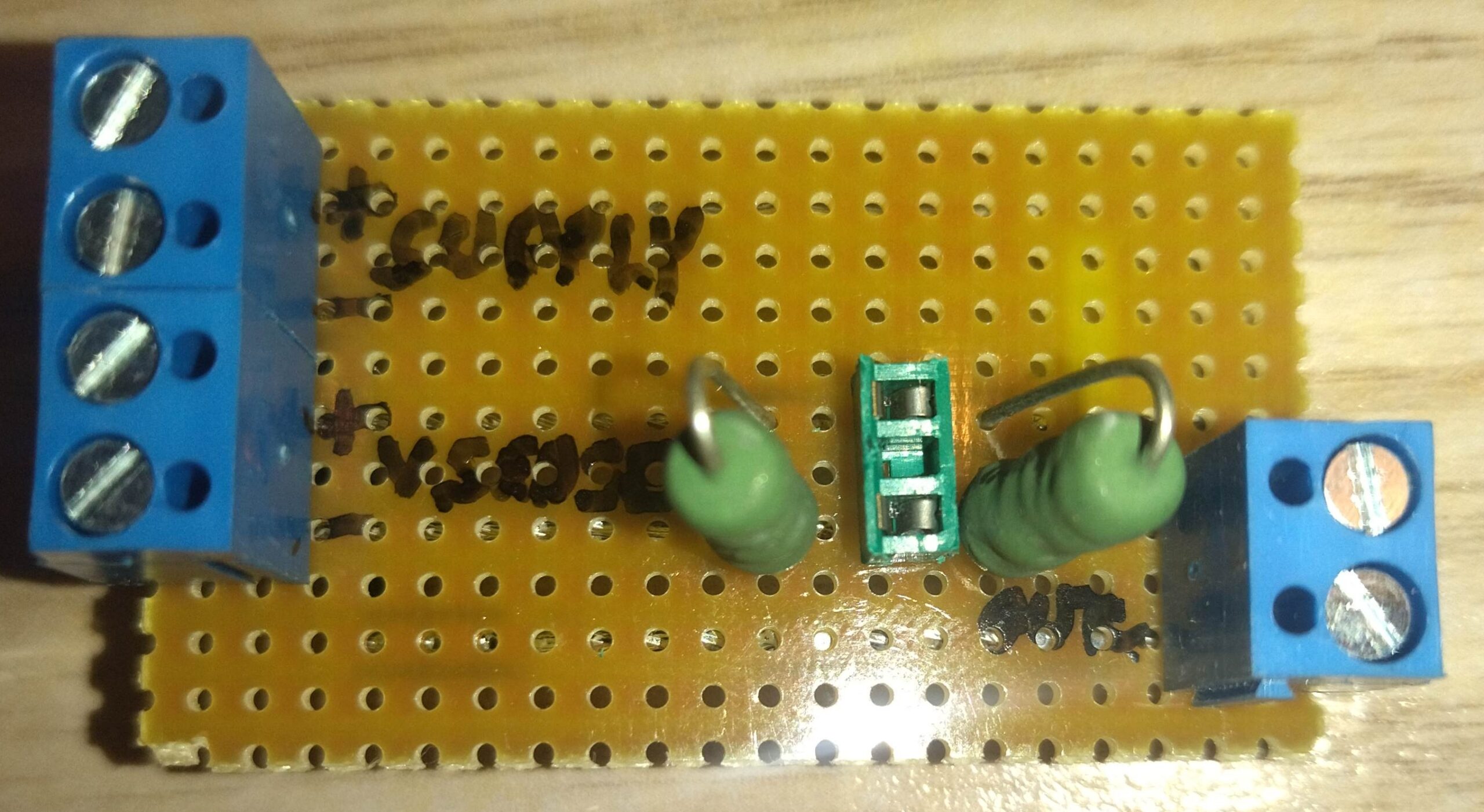
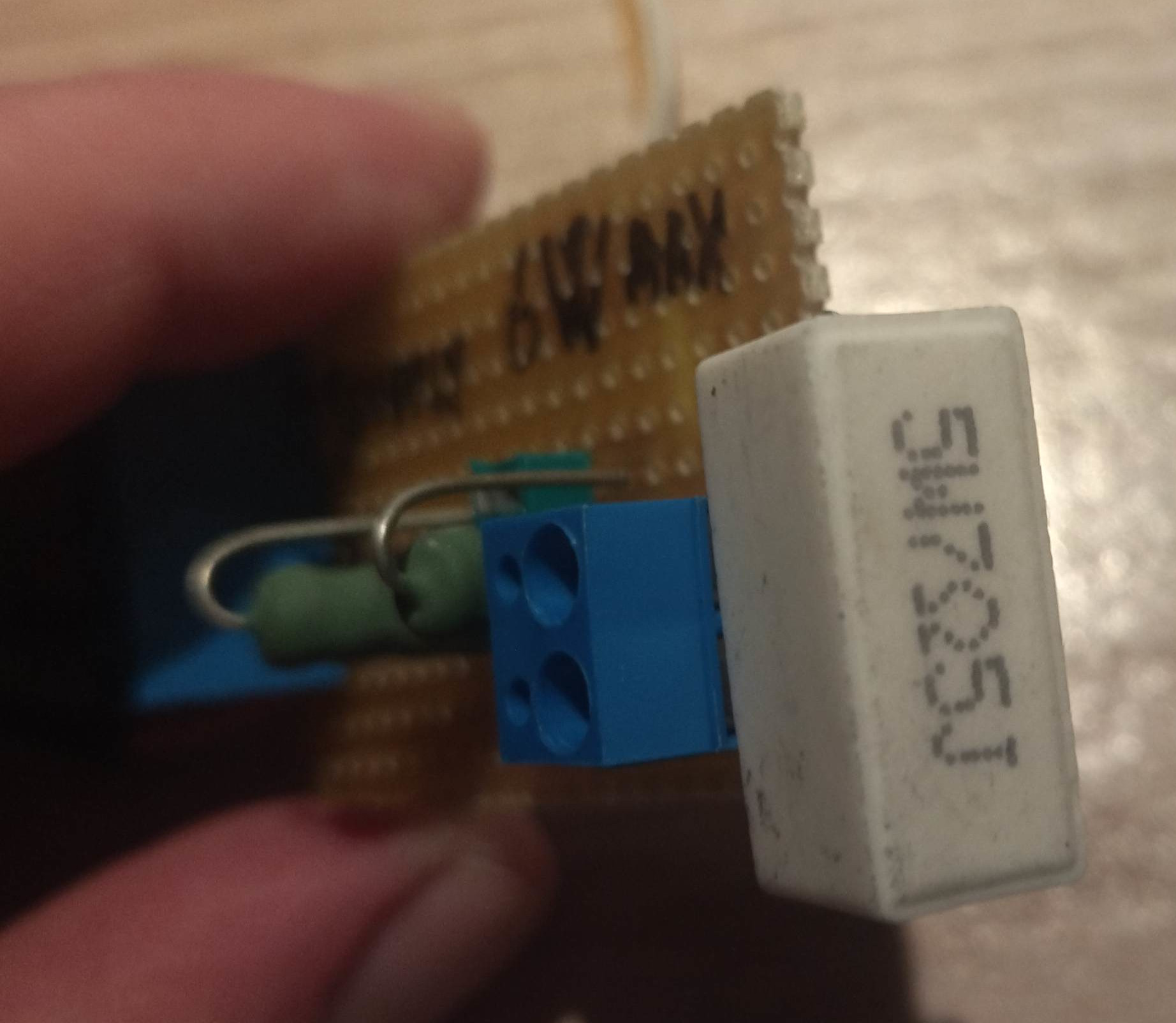
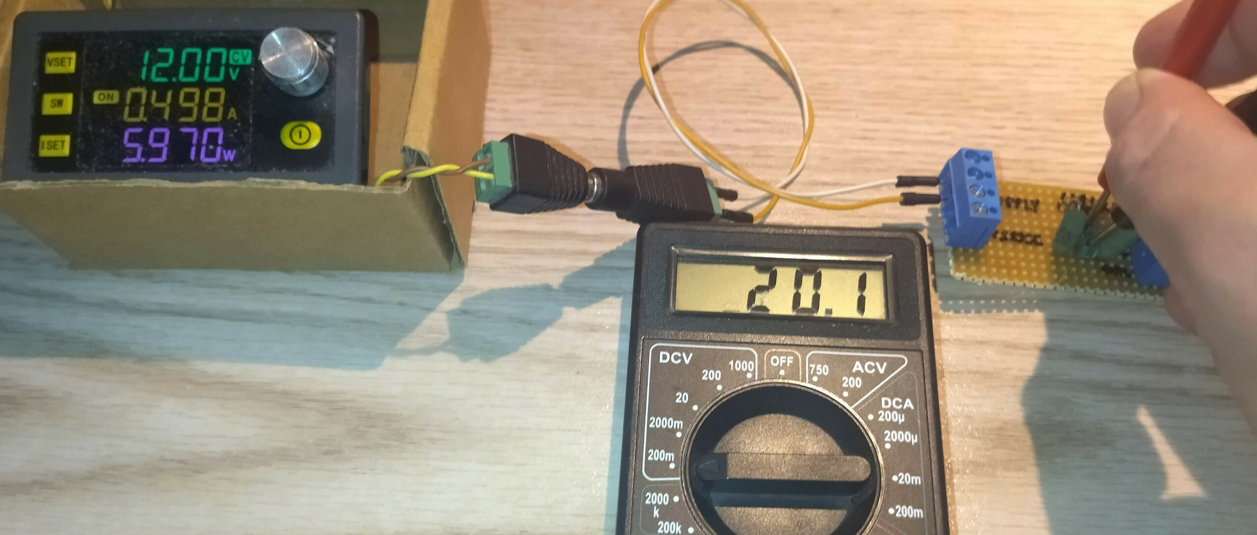
I needed a shunt to measure current, but only had two 0.082 Ω, 3W resistors. Luckily, I found them in a scrapped PSU.
Two resistors in parallel:
0.082 Ω || 0.082 Ω = 0.041 Ω, 6W total
But how accurate is the result? And does it matter if the voltmeter connects through sense terminals about 4 cm away from the resistors?
Time to experiment.
Method:
1. Connect a current-limiting bench PSU, a load resistor and the shunt in series.
2. Measure the current shown by the PSU and the voltage across the shunt.
3. Calculate the effective resistance using Ohm’s law: R = V / I
4. Compare the result with the nominal 0.041 Ω. Then measure through the separate sense terminals and compare the readings.
Results:
– Test 1 – 24 Ω load: 12 V PSU setting, 498 mA measured current, 20.1 mV across the shunt.
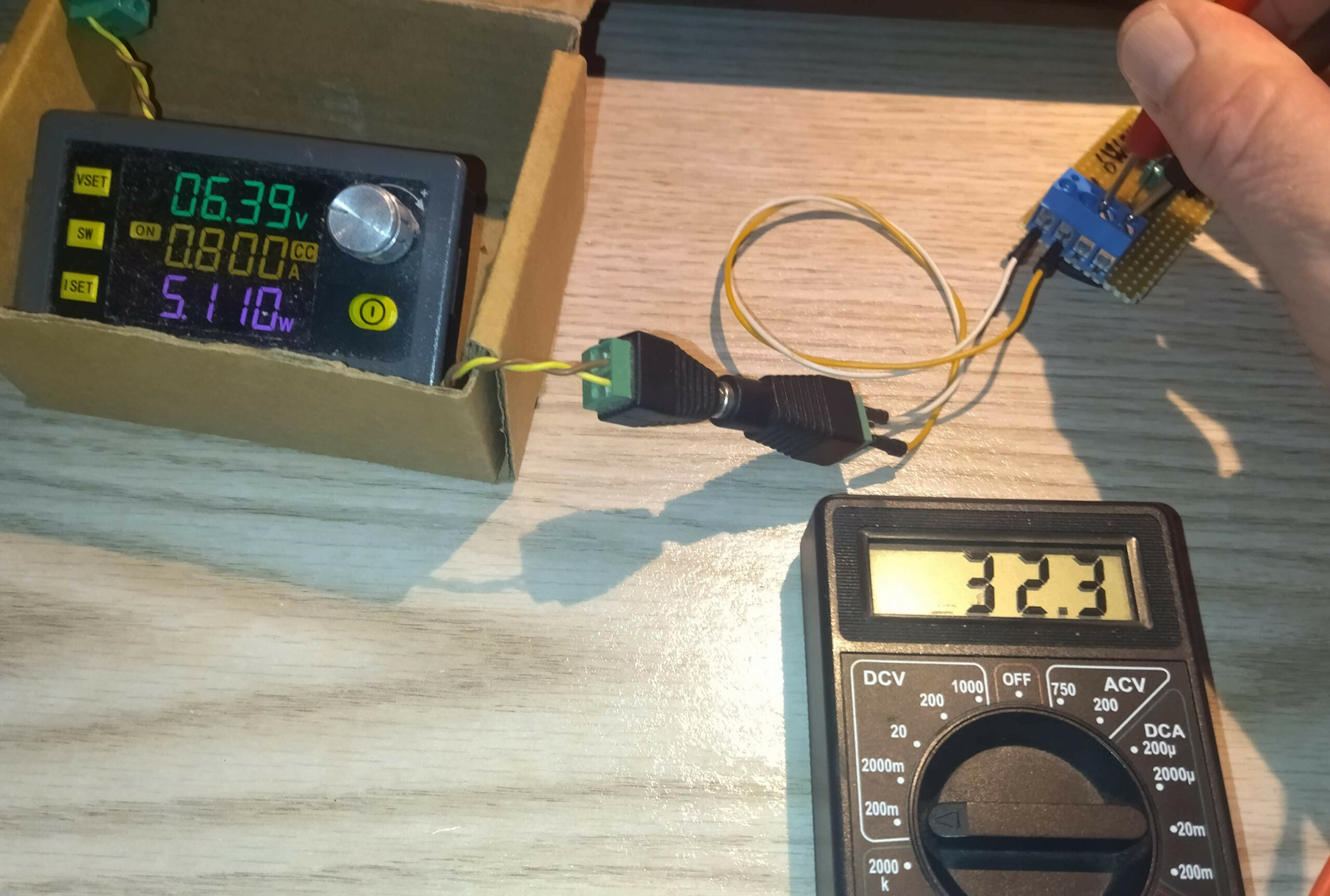
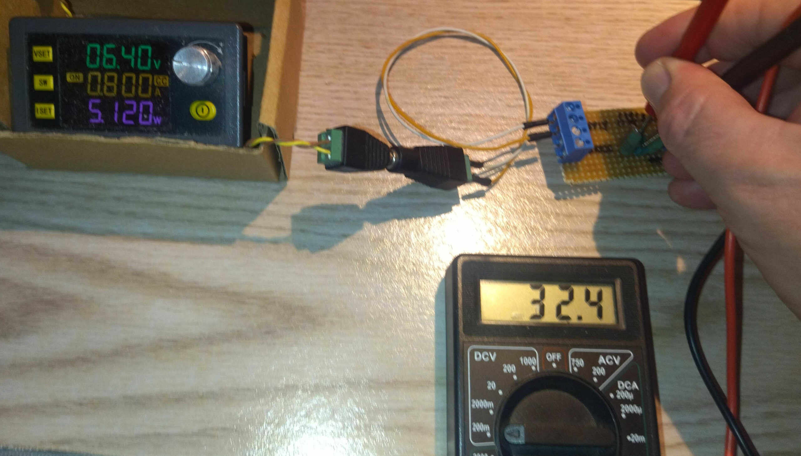
– Test 2 – 7.5 Ω load: 800 mA measured current, 32.4 mV directly across the shunt.
– Test 2 – sense terminals: 32.3 mV.
Calculated shunt resistance:
– Test 1: 20.1 mV / 0.498 A = 0.0404 Ω
– Test 2: 32.4 mV / 0.800 A = 0.0405 Ω
The two results agree remarkably well.
The sense terminals, approximately 4 cm away, gave a reading just 0.1 mV lower – a difference of about 0.3%.
One experiment, two useful findings:
– The effective resistance is close to the nominal 0.041 Ω.
– The separate sense terminals work well at these test currents.
Of course, this doesn’t establish the resistors’ exact tolerance or validate the assembly at high currents. That’s the next challenge.
General data:
– Shunt: 2 x 0.082 Ω in parallel
– Nominal resistance: 0.041 Ω
– Measured resistance: 0.0404-0.0405 Ω
– Test currents: 498 mA and 800 mA
– Sense-terminal distance: approximately 4 cm
– Measurement instrument: cheap digital multimeter
– Test source: current-limited bench PSU