
Posts
Popular Categories
- Builds (15)
- Calculators (5)
- Circuit Library (1)
- DIY (20)
- Engineering Education (5)
- KiCad Files (5)
- Notes (1)
- Product Updates (2)
- Schematic (17)
- Uncategorised (8)
Search the website
-
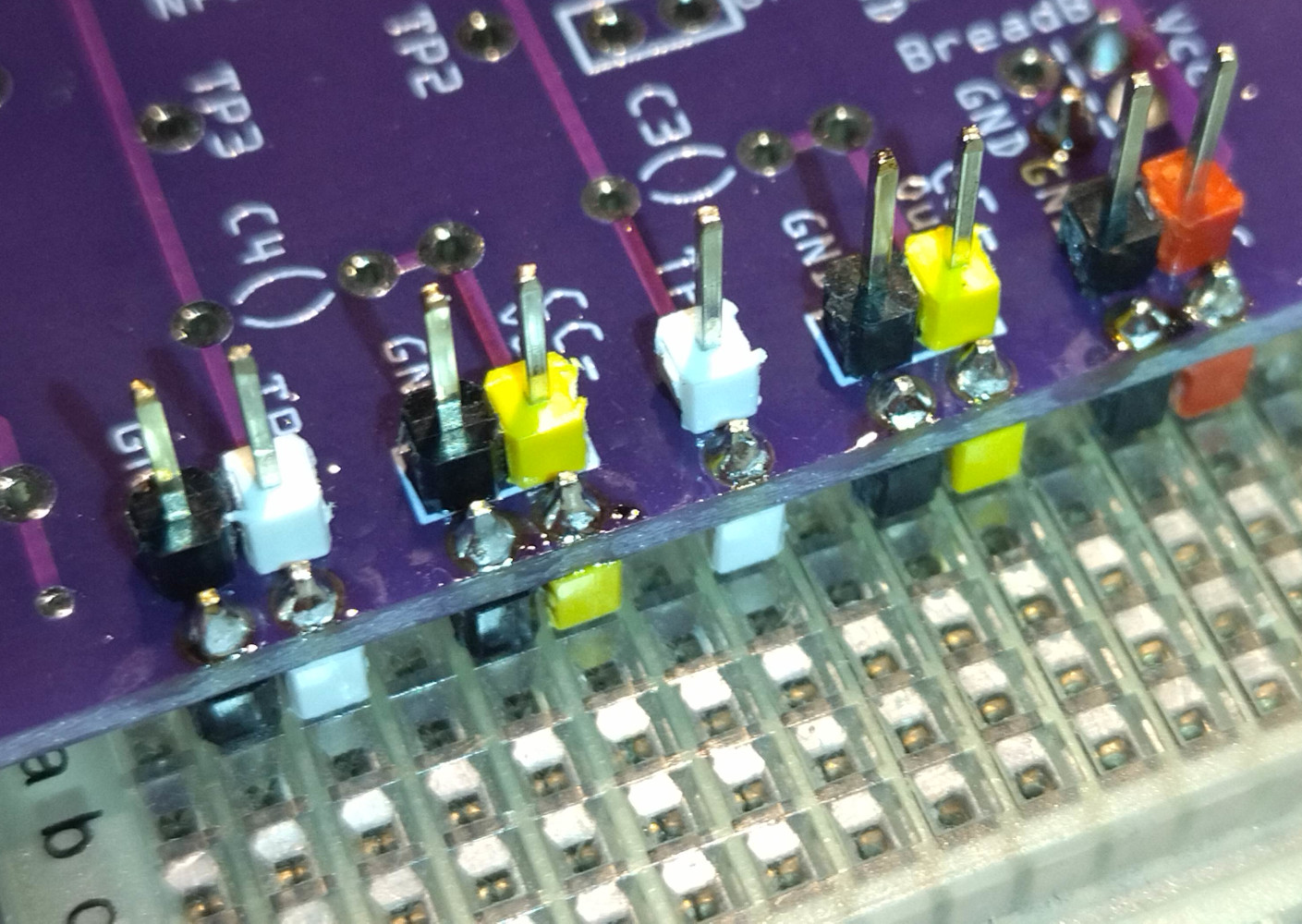
Extend experiments on to a breadboard
Extend the experiments on the input and the output side with the bottom faced pin headers with whatever on a breadboard. – And continue to use the pin headers on the top side for wires to whatever. You can even mount pin headers for the power rails on the breadboard.
-
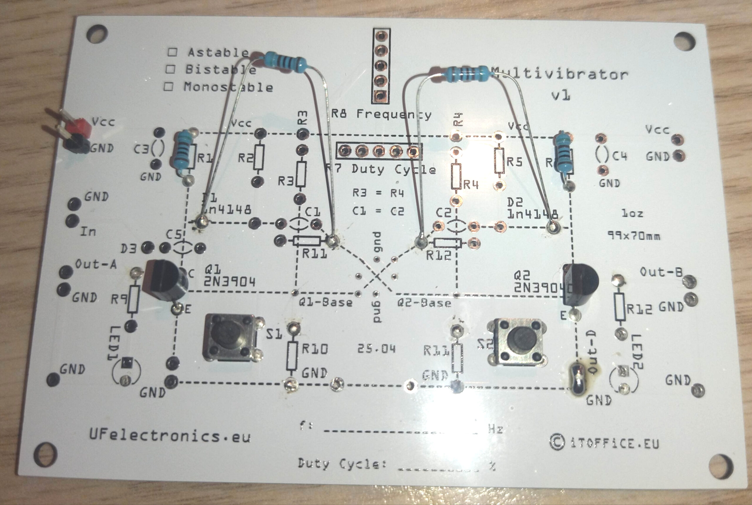
Triggered Bistable Multivibrator – Schematic and Build
PDF for downloading
-
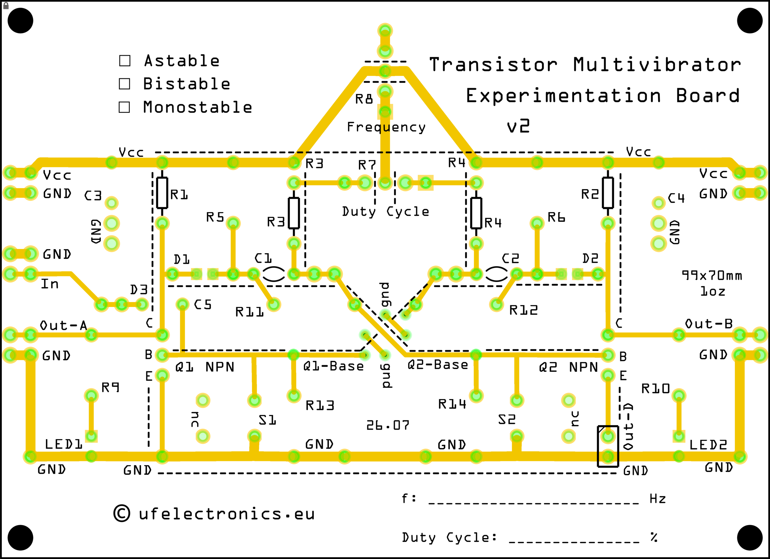
Schematic for a Simple 218 Hz Astable Multivibrator
Designed for the Transistor Multivibrator Experimentation Board, this circuit is a great introduction to transistor-based oscillators and multivibrator operation. BOM (Bill of materials) C1, C2: 100 nF (2x) JP1, JP2, Out-D1: Bridged (1x/3x) Q1, Q2: 2N3904 (2x) R1, R2: 2.2 kΩ (2x) R3, R4: 33 kΩ (2x) Version 2 of the PCB is coming this…