Description
Learn how transistor differential amplifiers really work – by building, measuring and experimenting.
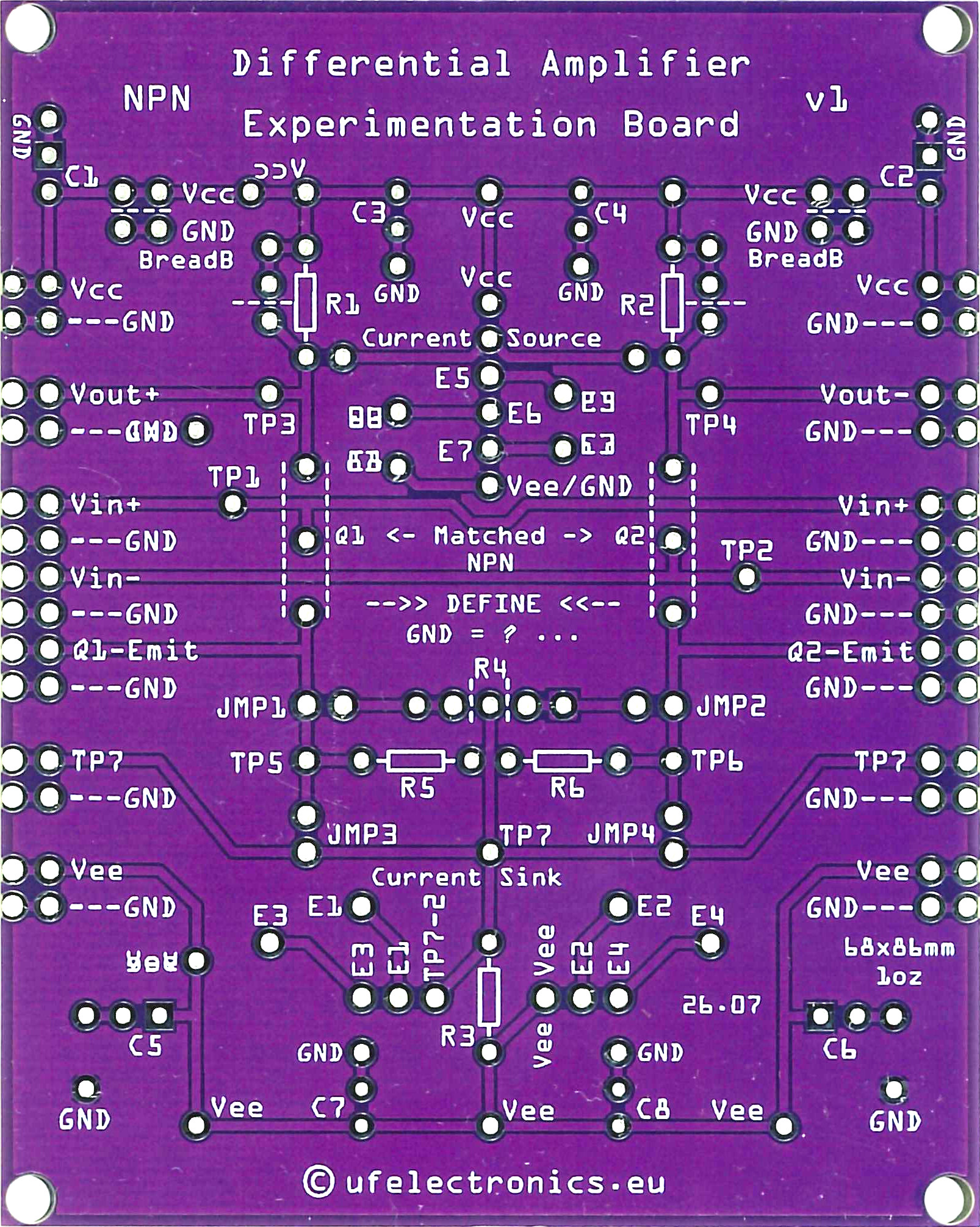
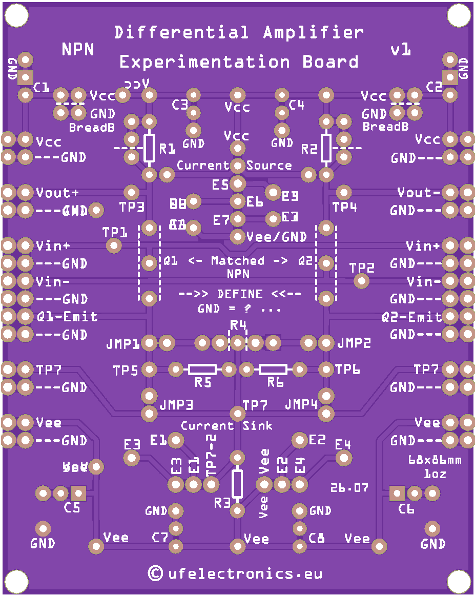
The Differential Amplifier Experimentation Board is a reusable learning platform designed for electronics hobbyists, engineering students, educators, and anyone interested in analog electronics.
Rather than repeatedly wiring differential amplifiers on a breadboard, this PCB provides a structured platform where you can quickly assemble, modify and compare different circuit configurations while observing how each design choice affects the amplifier’s performance.
Whether you are learning about differential pairs for the first time or preparing to understand operational amplifiers and analog integrated circuits, this board provides an excellent foundation.
Features
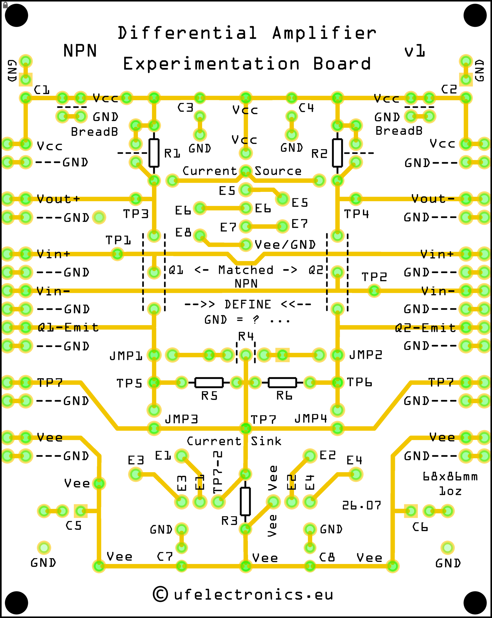
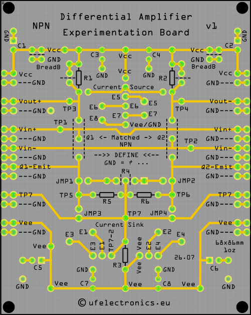
- Semi-schematic PCB layout for intuitive learning
- Visible signal routing on the component side
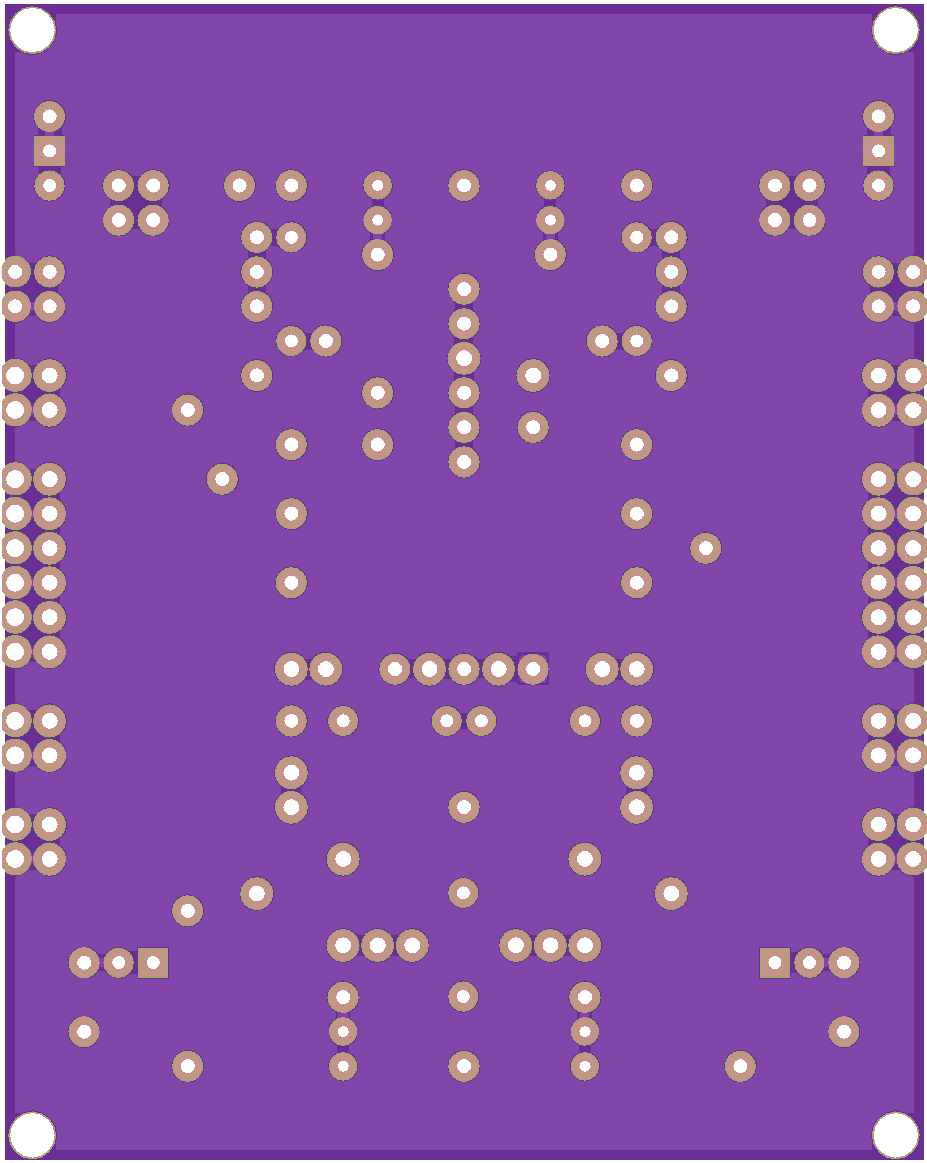
- Full bottom-side ground plane
- Through-hole components throughout
- Configurable differential amplifier
- Adjustable emitter degeneration
- Adjustable emitter resistor matching
- Supports both resistor-based and active current sources
- Supports both resistor-based and active current sinks
- Dedicated footprints for external Current Source and Current Sink boards
- Multiple oscilloscope-friendly test points
- Dual differential outputs (Vout+ and Vout−)
- Differential inputs (Vin+ and Vin−)
- Breadboard expansion connectors
- Eight optional decoupling capacitor footprints
- Designed specifically for modification and experimentation
What You Will Learn
The board allows you to explore topics such as:
- Differential amplifier operation
- Differential and common-mode signals
- Common-Mode Rejection Ratio (CMRR)
- Voltage gain
- Current sources
- Current sinks
- Current mirrors
- Wilson current mirrors
- Active collector loads
- Emitter degeneration
- Transistor matching
- Small-signal analysis
- Operating-point calculations
- Biasing techniques
- Analog design trade-offs
These are the same concepts used inside operational amplifiers, instrumentation amplifiers and many analog integrated circuits.
Designed for Experimentation
Unlike a traditional PCB intended for one fixed circuit, this board encourages experimentation.
You can begin with a simple differential amplifier using collector and tail resistors, then progressively improve the design by adding:
- emitter degeneration
- adjustable emitter matching
- active current sinks
- active current sources
- transistor current mirrors
- JFET current sinks
- external breadboard circuits
The numerous test points and breadboard expansion connectors make it easy to observe internal voltages, inject signals and evaluate circuit performance using an oscilloscope or multimeter.
Included Documentation
The board is accompanied by a comprehensive 41-page illustrated manual containing:
- Step-by-step circuit explanations
- Analog electronics theory
- AC analysis
- Small-signal calculations
- Gain calculations
- Current-source and current-sink examples
- Wilson current mirror discussion
- Practical design notes
- Circuit notation guide
- Nine guided laboratory experiments
- Assembly sheet
- Semi-schematic PCB layout
The documentation is designed as a practical learning resource rather than a simple assembly guide.
Download the documentation here:
Differential Amplifier Experimentation Board v1 – Rev 2
( Rev. 1 )
Suggested Experiments
The included documentation guides you through experiments including:
- Basic differential amplifier
- Emitter degeneration
- Active current sink
- Active current source
- Voltage gain measurements
- Common-Mode Rejection Ratio (CMRR)
- Transistor matching
- JFET current sink
- Differential versus common-mode signals
Each experiment includes measurement suggestions together with questions designed to encourage deeper understanding of the circuit.
Target Audience
This board is suitable for:
- Electronics hobbyists
- Makers
- Engineering students
- University laboratories
- Technical colleges
- Electronics educators
- Self-study in analog electronics
- Anyone preparing to learn operational amplifier design
Through-Hole Design
All components are through-hole, making assembly straightforward and allowing components to be replaced repeatedly during experiments.
The semi-schematic layout and visible routing help bridge the gap between circuit diagrams and real hardware, making it easier to understand how electronic schematics become physical circuits.
Designed by Engineers for Learning
Most differential amplifier circuits found online are intended to perform a specific task.
This board is different.
It has been designed from the ground up as an educational platform where every section of the PCB encourages experimentation, measurement and comparison. Instead of simply building a circuit that works, you will learn why it works—and how each improvement affects its performance
Specifications
- Through-hole PCB
- Differential amplifier based on NPN transistors
- Dual-supply operation (recommended)
- Multiple test points
- Breadboard expansion headers
- Compatible with external Current Source and Current Sink boards
- Designed for oscilloscope-based laboratory work
- Extensive illustrated documentation included