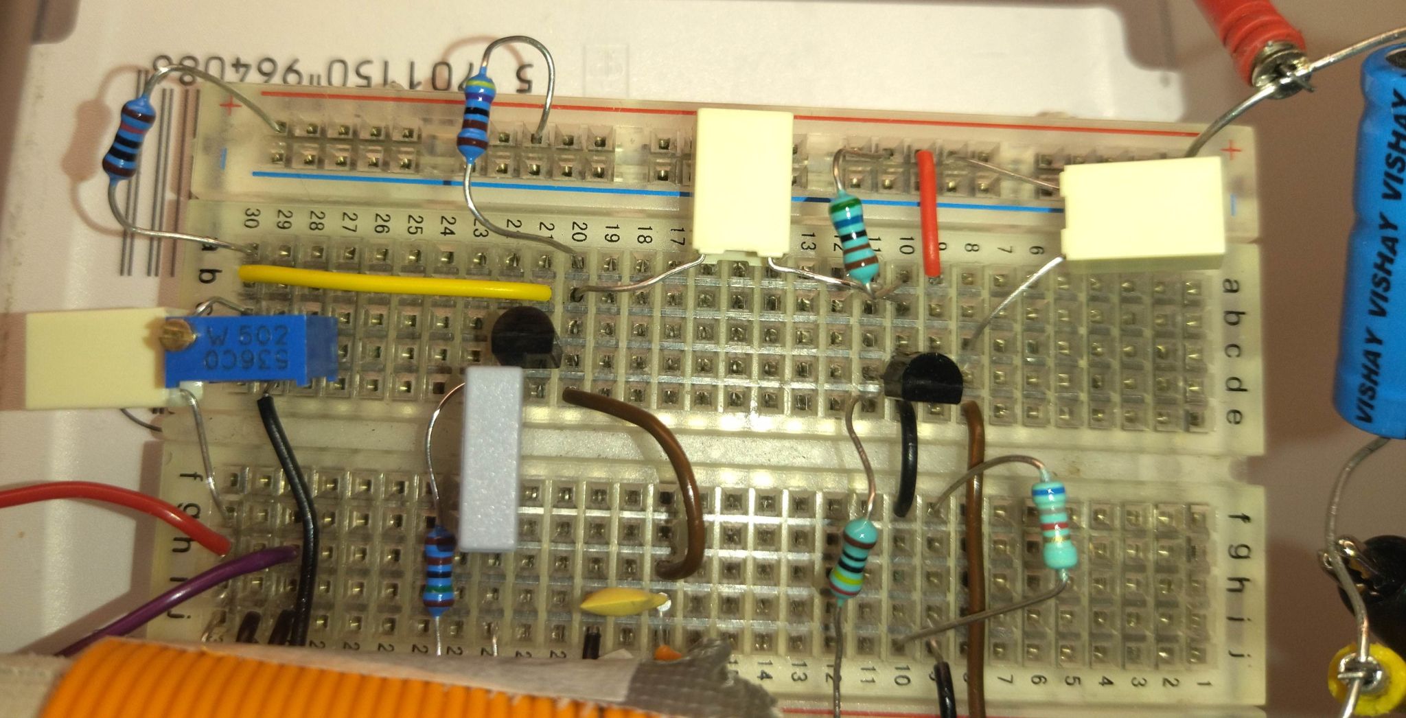
This oscillator is based on two transistors. No crystals, by purpose.
It can oscillate on various frequencies between 4.8 MHz and 8 MHz.
With a variable capacitor (around 15 – 400 pF) instead of C2, you can dynamically vary the frequency in parts of that range.
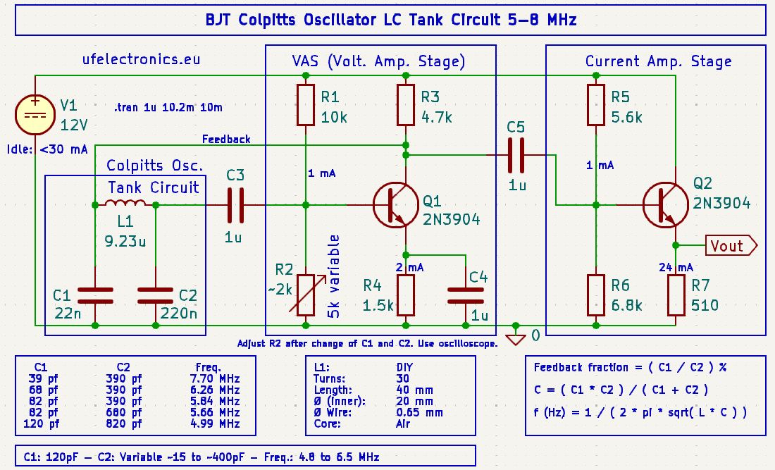
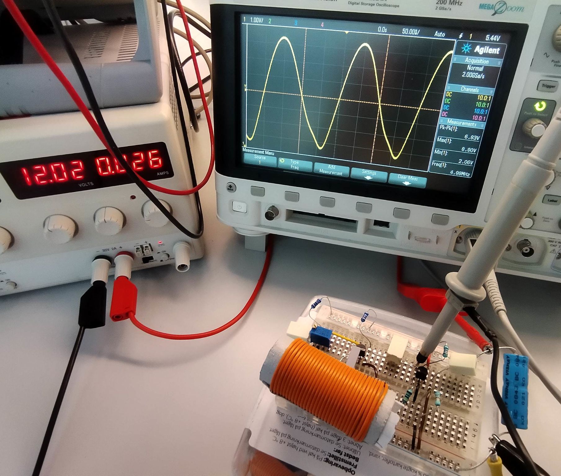
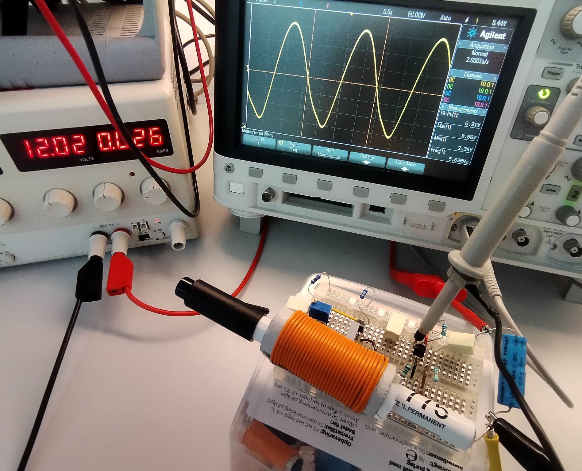
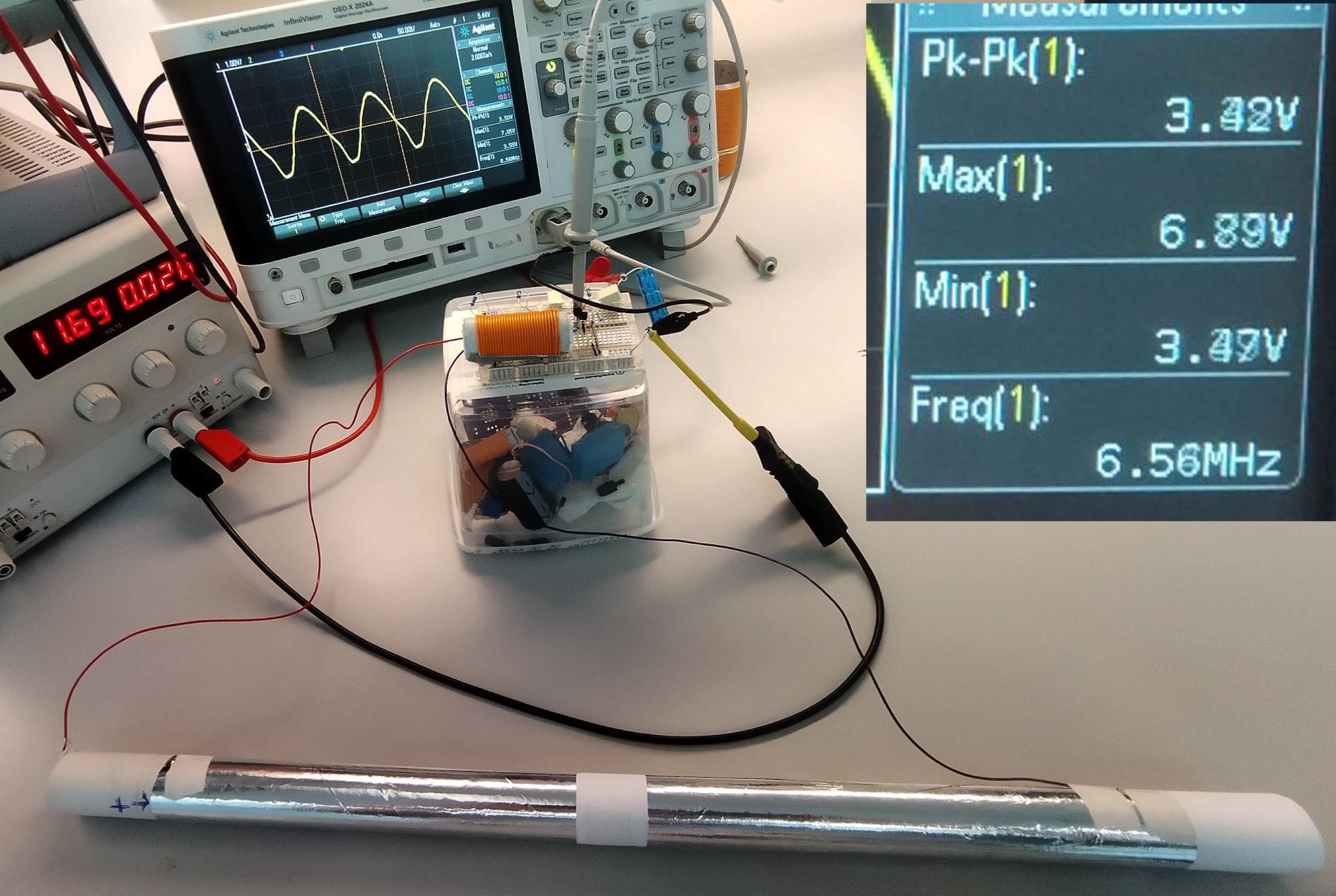
Its functionlity is verified by real world build and testing. Not by simulation.
One image shows how an aluminium pen changs the frequency from 4.99 MHz to 5.6 Mhz. – Try out a ferrite rod and see how it reacts, if you have one.
Other images show how a DIY variable capactor between 15 and 650 pF changes the frequency between 4.88 MHz and 6.5 MHz.
The DIY cap is explained in a previous post:
https://ufelectronics.eu/16-pf-to-650-pf-diy-variable-capacitor/
The inductor is a DIY version. See the schematic for details. Building one is explained in this post:
https://ufelectronics.eu/how-to-wind-a-perfect-diy-inductor/
Download the KiCad simulation schematic for free from Github:
https://github.com/ufelectronics/Colpitts_Osc_BJT_5-8_MHzhttps://lnkd.in/ehFkiwUa
Next experiment might be using a crystal instead of the LC resonator. Few components needs to be exchanged for that.
This might not be the best oscillator as such. So you are welcomed to suggestions improvements in the comments.