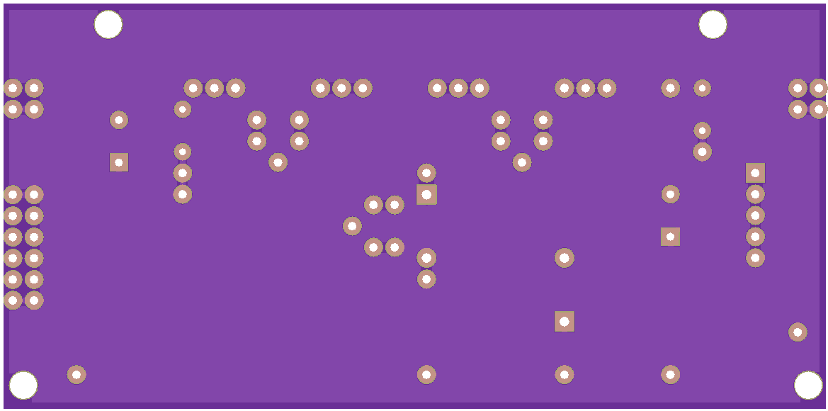
Description
Build, modify and explore switching power converters.
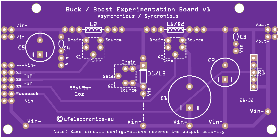
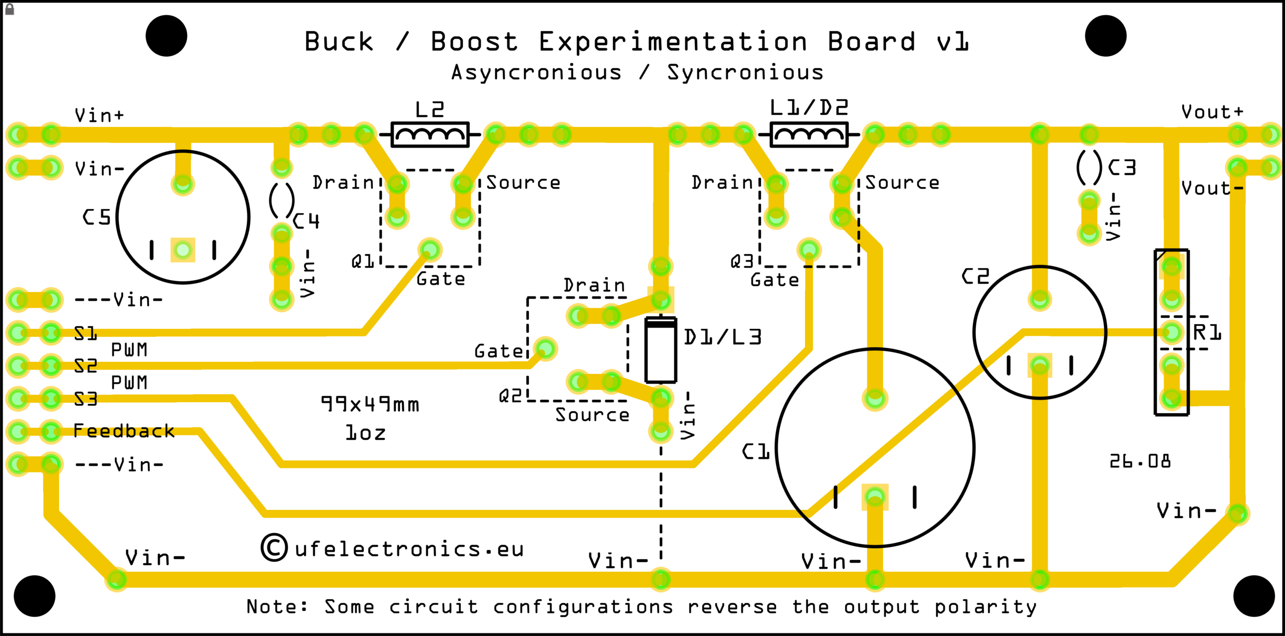
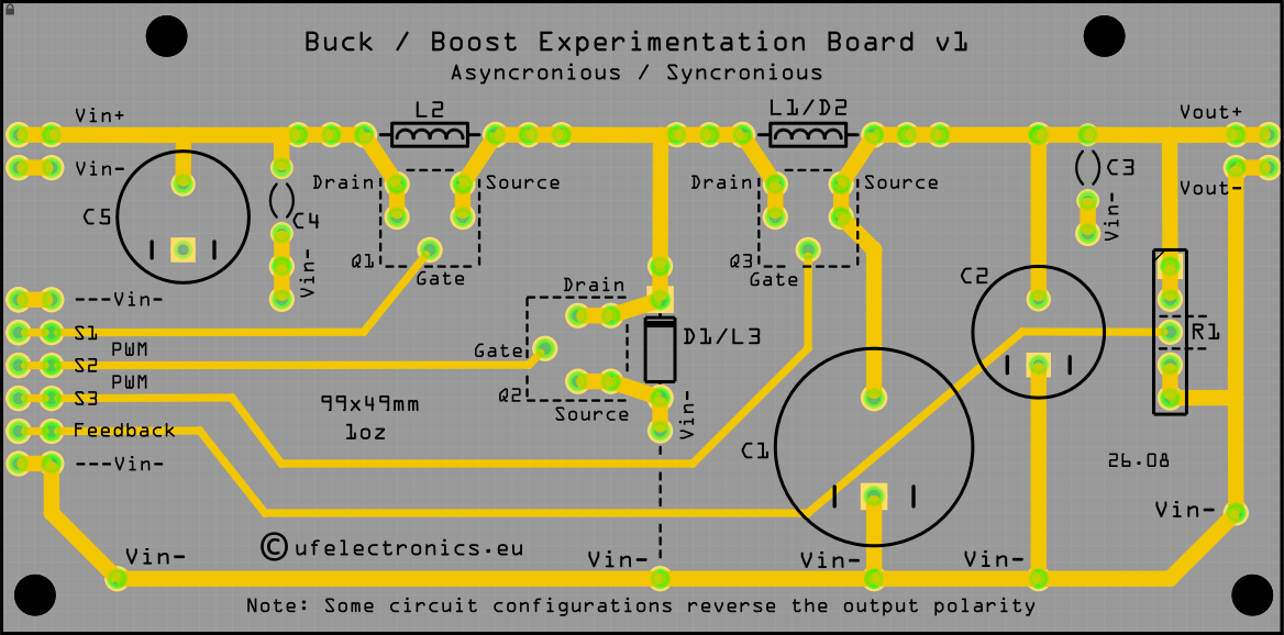
The Buck / Boost Experimentation Board is a practical learning platform for exploring the fundamental principles of switching DC/DC converters.
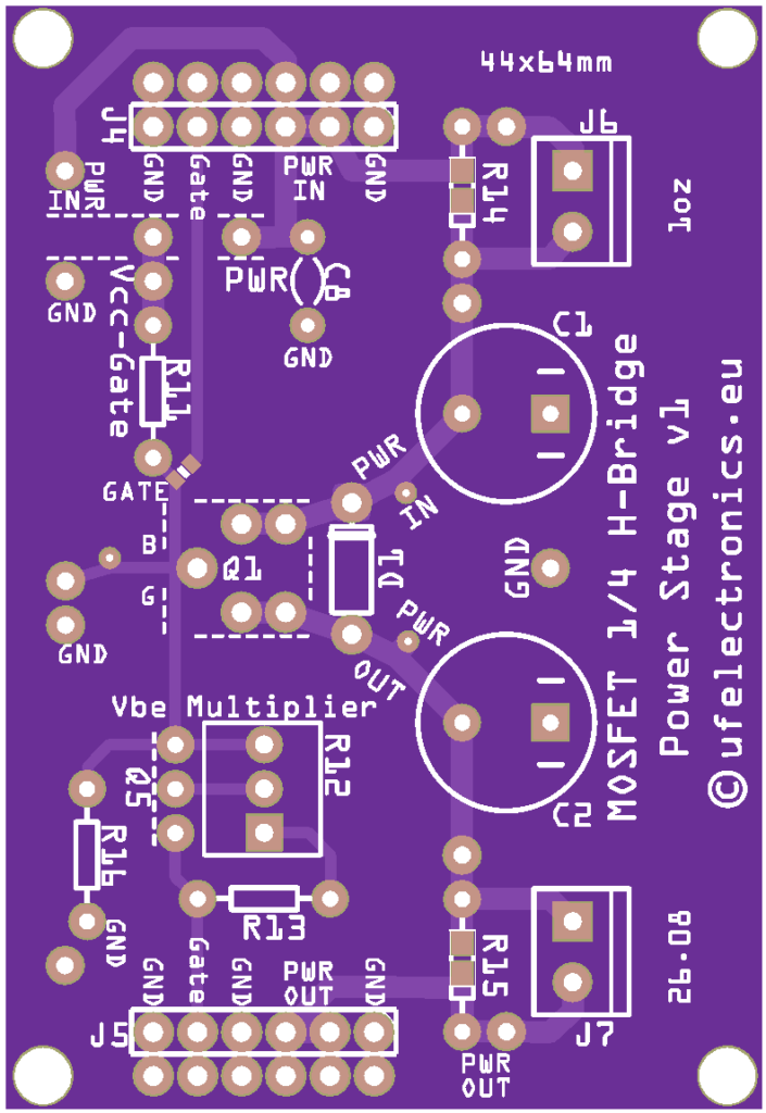
Instead of hiding the switching process inside a dedicated converter IC, the MOSFET control signals are brought directly to accessible pin headers. This allows the board to be driven by an external PWM source, giving students and experimenters direct control over the switching behaviour.
The board can be configured for buck, boost and buck-boost operation, making it possible to investigate how the same basic components can be arranged to produce very different converter behaviours.
It is designed around the principle:
Build it. Change it. Measure it. Understand it.
What can you build?
The board can be configured for several fundamental switching-converter topologies.
Buck Converter
Build a step-down converter and investigate how the switching duty cycle affects the output voltage.
Experiment with:
- Input and output voltage
- PWM duty cycle
- Switching frequency
- Inductor value
- Capacitor value
- Load resistance
- Voltage and current ripple
- Efficiency
Boost Converter
Reconfigure the board as a step-up converter and explore how energy is stored in the inductor and transferred to the output.
Experiment with:
- Output voltage versus duty cycle
- Inductor current
- Switching frequency
- Output ripple
- Load
- Efficiency
- Continuous and discontinuous operation
Buck-Boost Converter
The board can also be configured as a buck-boost converter.
This allows you to investigate a topology where the output voltage can be either lower or higher in magnitude than the input voltage.
Depending on the configuration, the output polarity can also be reversed. Always check the circuit configuration and output polarity before connecting a load or measuring equipment.
Asynchronous or synchronous operation
The board can be used to explore both asynchronous and synchronous switching.
In an asynchronous converter, a diode provides the rectification path.
In a synchronous configuration, a second MOSFET can be used instead of the diode, allowing the learner to investigate synchronous rectification and compare its behaviour with the simpler diode-based circuit.
This makes it possible to progress from a very simple converter to a more advanced configuration without changing the basic experimentation platform.
External PWM Control
The MOSFET gate connections are brought directly to pin headers.
No PWM controller is built into the board.
This is intentional.
The switching signal can come from practically any suitable external source, such as:
- A microcontroller
- An Arduino or similar development board
- A function generator
- A dedicated PWM generator
- A 555-based PWM circuit
- An external gate-driver circuit
- Other suitable digital or analogue control circuitry
This gives the learner direct control over the most important switching parameters.
The board becomes the power stage, while the student chooses how the MOSFETs are controlled.
Use with the MOSFET Gate Driver Experimentation Board
The Buck / Boost Experimentation Board can also be used together with the MOSFET Gate Driver Experimentation Board.
The gate-driver board provides a convenient way to experiment with MOSFET gate driving while still requiring an external control signal.
That control signal can originate from a microcontroller, PWM generator, 555 circuit, function generator or another suitable source.
This creates a useful progression:
PWM source → Gate Driver → Buck / Boost Converter
Students can therefore investigate the complete signal path from the generation of a control signal to the switching of the power stage.
Designed for Learning by Doing
The board is intentionally not a black-box DC/DC converter.
There is no fixed switching controller deciding what happens inside the circuit.
Instead, the important nodes and control signals are accessible so that the learner can:
- Build the circuit
- Change component values
- Change the topology
- Change the PWM signal
- Measure voltages
- Observe waveforms
- Measure currents
- Investigate losses
- Compare different configurations
- Discover what happens when the circuit is changed
An oscilloscope and a multimeter can turn the board into a powerful laboratory exercise.
What you can investigate
The board provides a practical way to explore topics such as:
- Switching converters
- PWM control
- MOSFET switching
- Inductor energy storage
- Diode rectification
- Synchronous rectification
- Buck conversion
- Boost conversion
- Buck-boost conversion
- Duty cycle
- Switching frequency
- Inductor current
- Output voltage ripple
- Input and output current
- Load regulation
- Conversion efficiency
- Continuous conduction mode
- Discontinuous conduction mode
- MOSFET gate drive
- Switching losses
A platform rather than a finished circuit
The same PCB can become several different experiments.
Start with a simple diode-based buck converter.
Then change the connections and investigate a boost converter.
Move on to a buck-boost configuration.
Replace the rectifier diode with a MOSFET and investigate synchronous operation.
Change the PWM frequency. Change the duty cycle. Change the inductor. Change the load.
The circuit is yours to experiment with.
Recommended equipment
The board does not require a specific controller or development platform.
Depending on the experiment, useful equipment includes:
- DC power supply
- PWM source or function generator
- Microcontroller or development board
- Oscilloscope
- Multimeter
- Electronic load or suitable resistive load
- External MOSFET gate driver, where appropriate
Important
This is an experimentation board, not a complete DC/DC converter module.
The user is responsible for providing the appropriate PWM/control signals, power supply, load and, where required, MOSFET gate-drive circuitry.
Care must be taken with switching voltages, currents, inductive loads and output polarity.
Some circuit configurations reverse the output polarity. Always verify the configuration and measure the output before connecting a load.