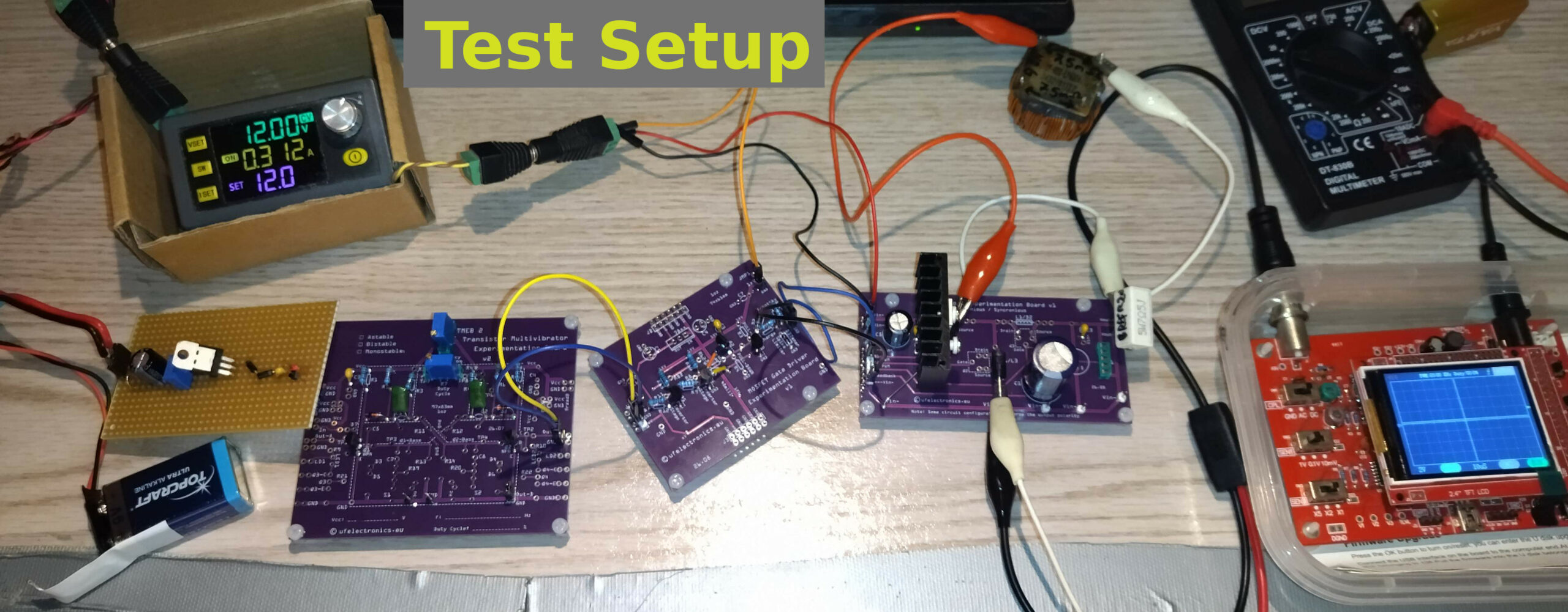
– Built with discrete components by design (no ICs), and deliberately kept simple to make it suitable for DIY. –
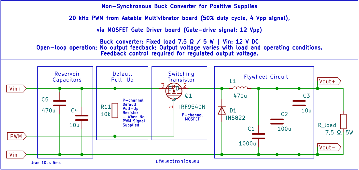
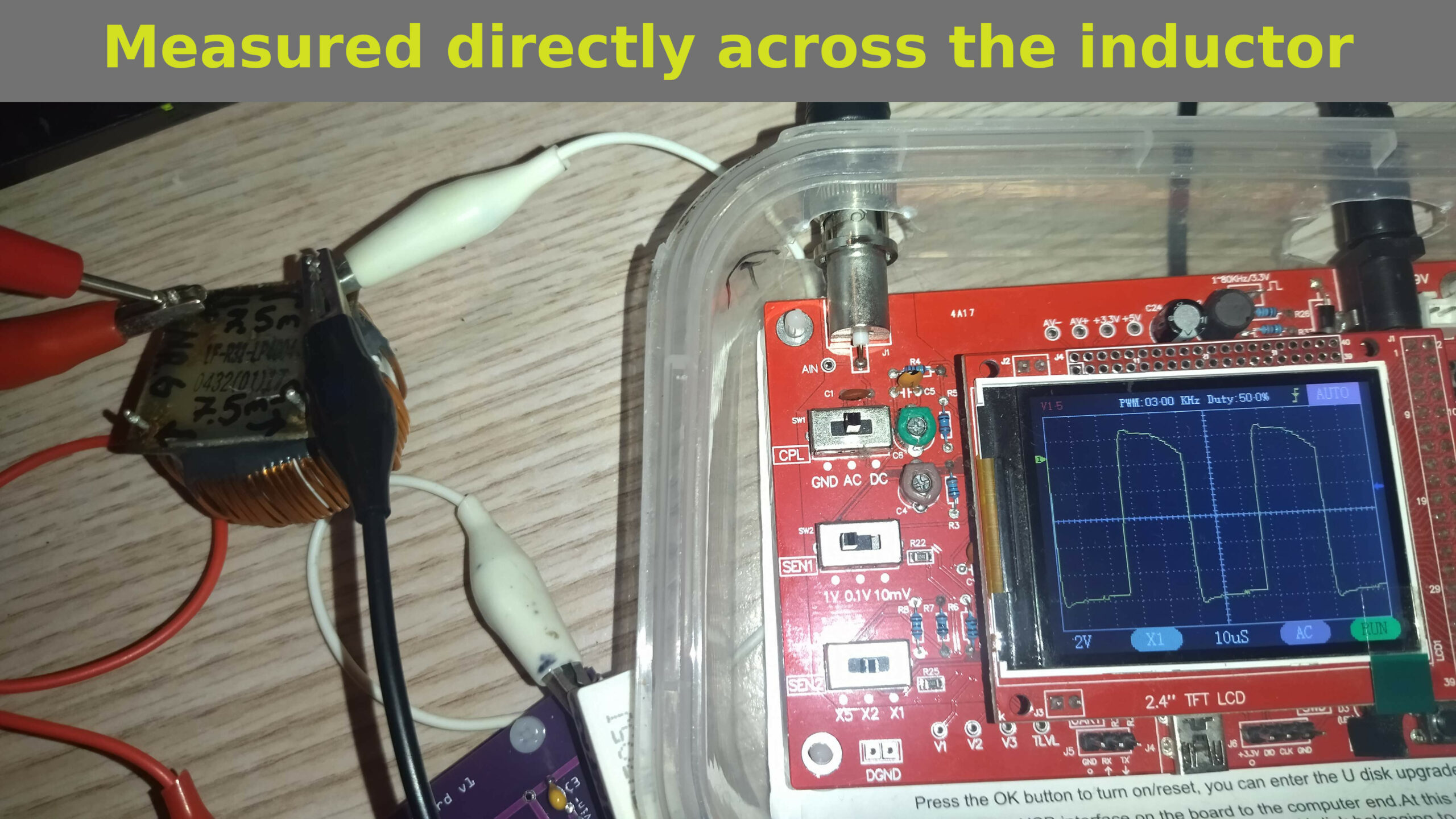
It is a simple, open-loop, non-synchronous buck converter. It uses a 20 kHz, 50% duty-cycle astable multivibrator as the PWM signal source, a discrete transistor push-pull gate driver and a P-channel as the high-side switch.
P- vs N-channel
A P-channel MOSFET simplifies high-side switching and is a practical choice for moderate currents, such as below ~4 A.
For higher currents, an N-channel MOSFET often offers lower R_DS(on) and lower conduction losses. However, its gate voltage must rise above its source voltage to keep it fully on. A bootstrap or charge-pump driver can provide the required gate voltage.
The result at the moment?…
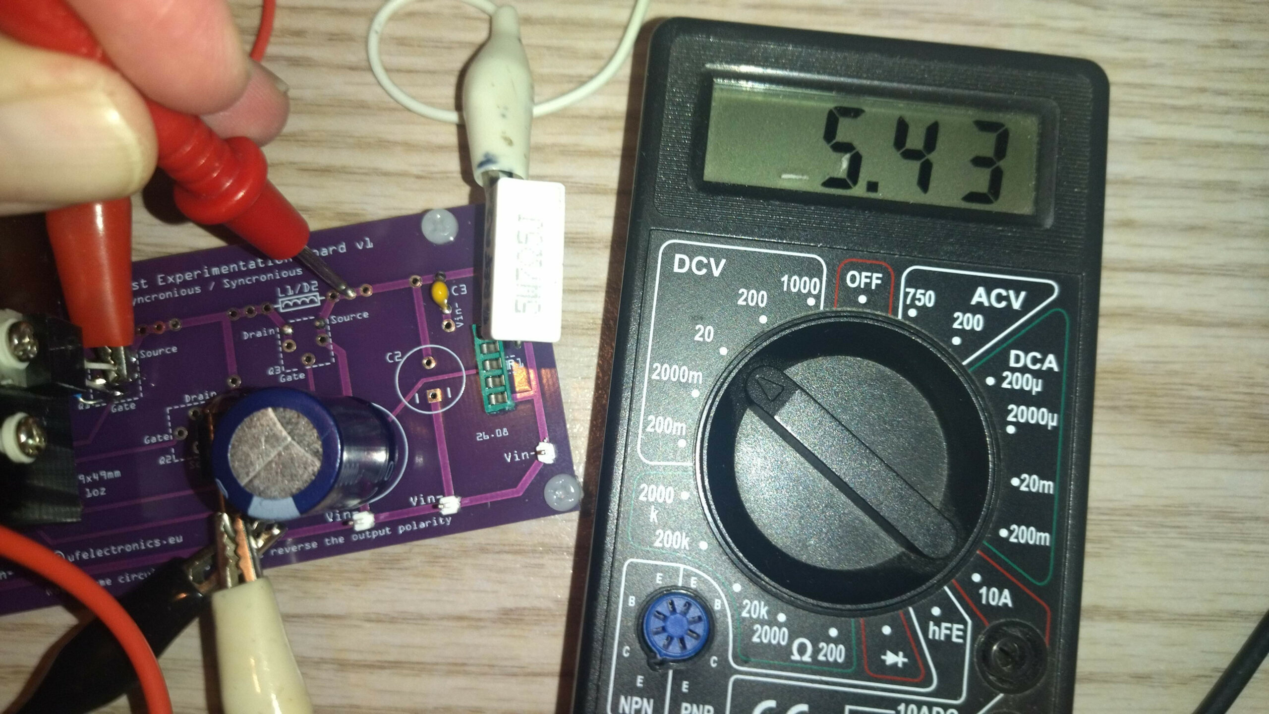
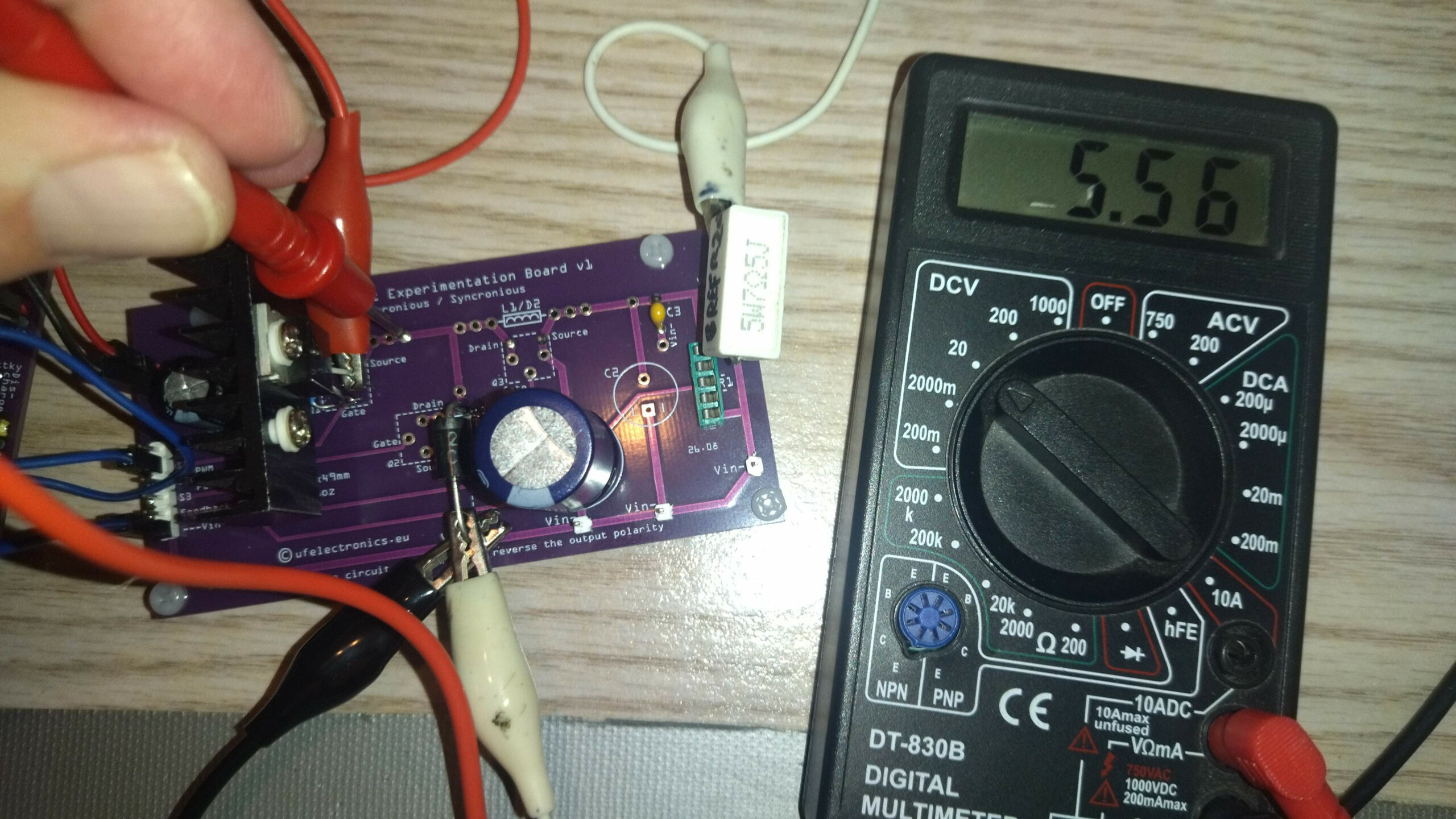
A working converter delivering 5.32 V from a 12 V supply, with ~80% estimated efficiency.
The output isn’t a standard 5 V or 6 V, but adjusting the duty cycle could bring it closer to either. The goal wasn’t a finished power supply, though – just a working circuit to verify basic functionality under a fixed load.
Next step: Adding feedback control to regulate the output voltage as the load changes. – Give me a few weeks. This is a side project.
Technical data:
* Input voltage: 12 V DC
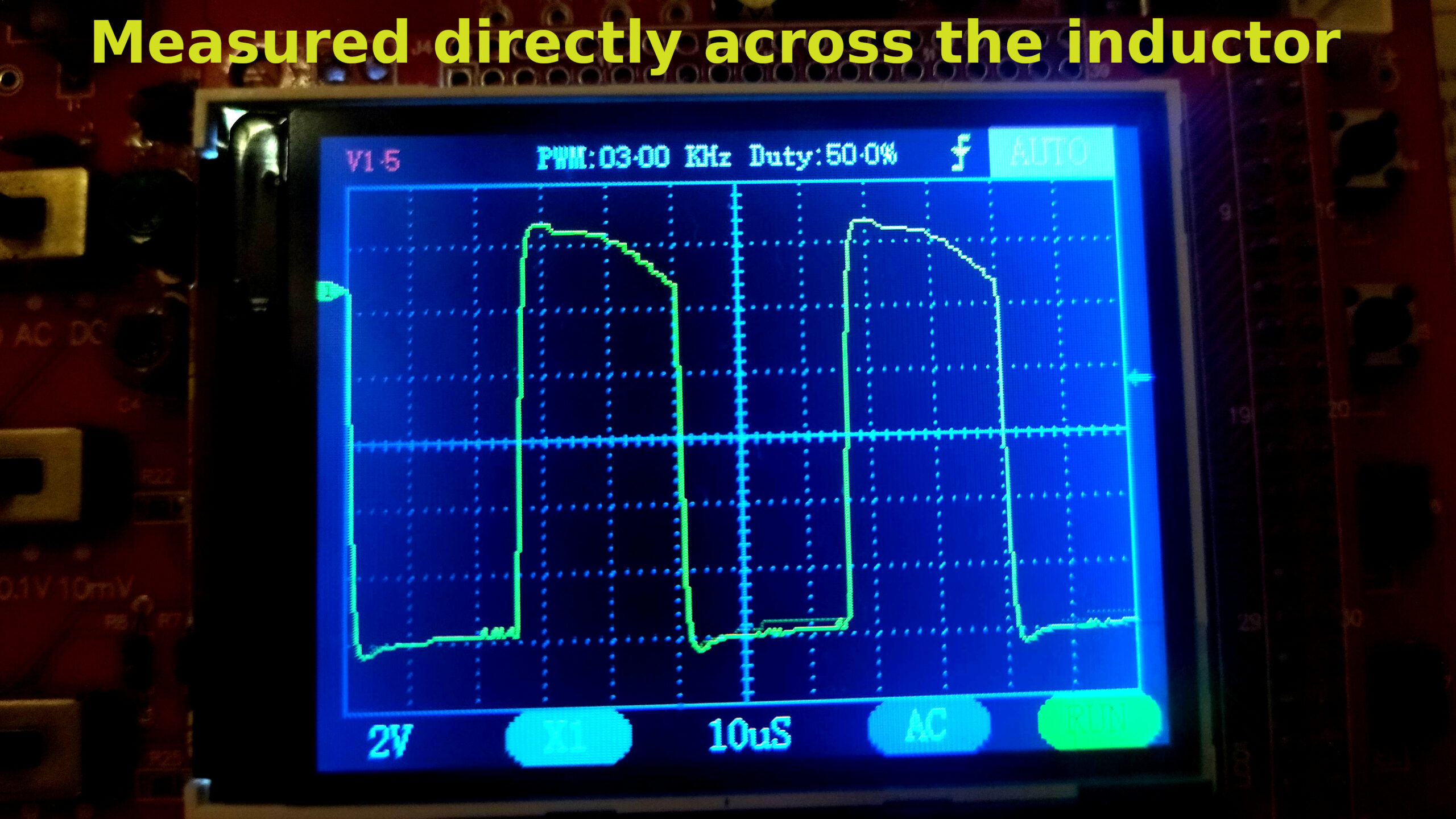
* Switching frequency: 20 kHz
* PWM duty cycle: 50%
* Ideal output voltage: 6.0 V
* Inductor used: Unknown inductance (salvaged)
* Measured output voltage: 5.32 V
* Load: 7.5 Ω / 5 W
* Output power: 3.77 W
* Total input current: 395 mA
* Estimated overall efficiency: ~80%