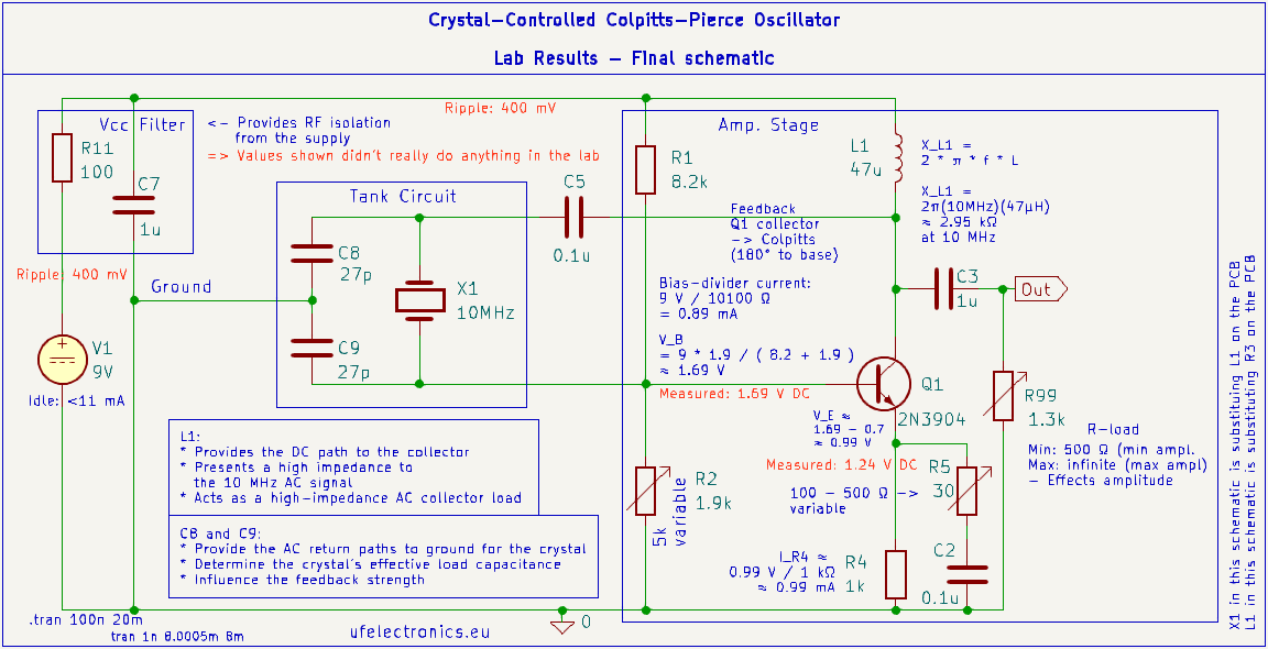
The circuit has been built and tested on the bench. Below are some measurements from testing different component values and operating conditions.
R5 – Emitter Resistor
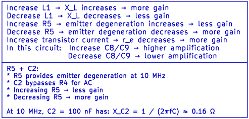
R5 = 30 Ω
- 4.74 Vpp
- 5.90 V min
- 10.64 V max
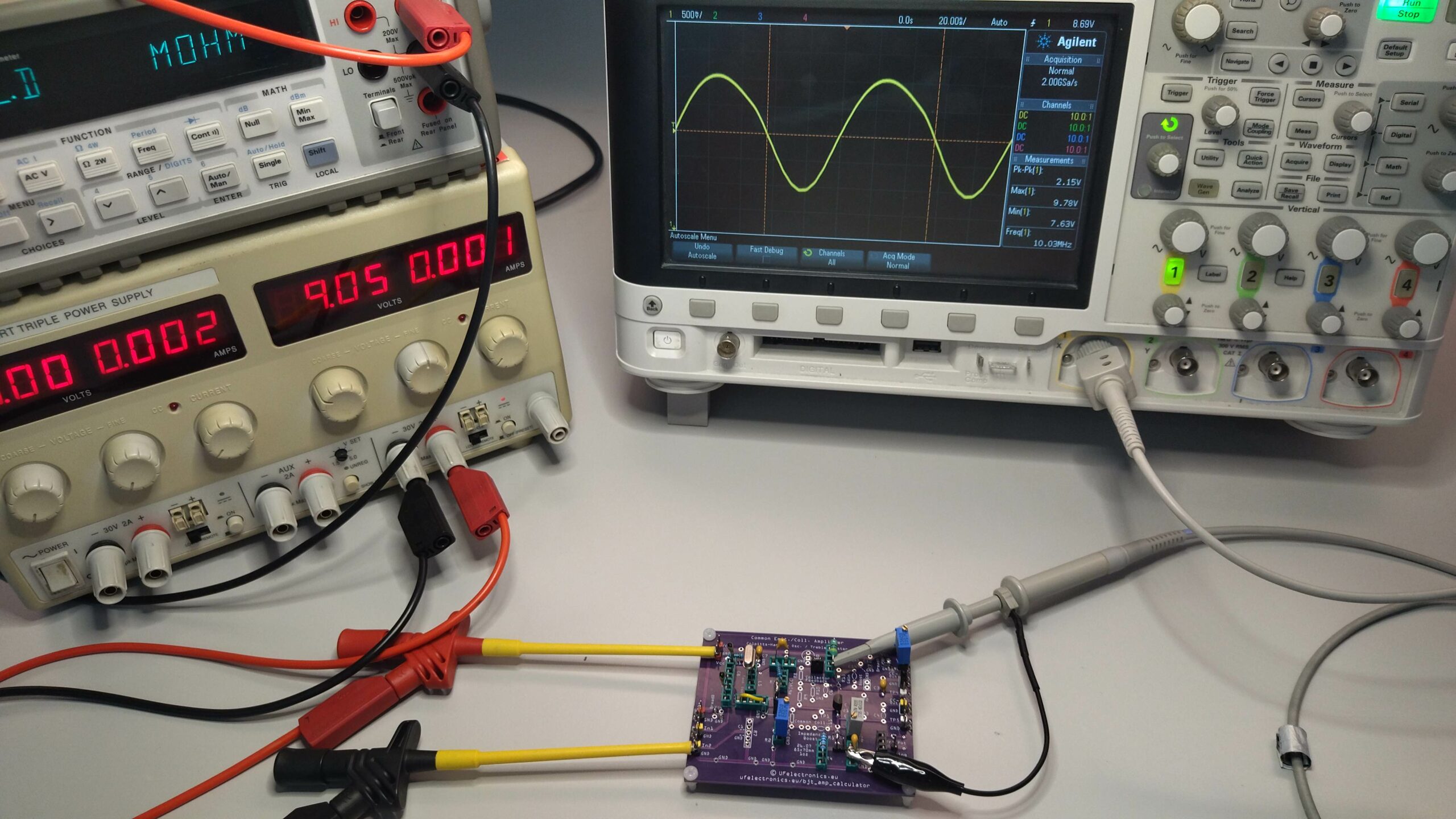
R5 = 200 Ω
- 2.17 Vpp
- 7.63 V min
- 9.80 V max
Interestingly, the lower-amplitude waveform looks visually cleaner.
An output amplifier may be required depending on the application, so there is little reason to drive the oscillator harder than necessary.
For now, 200 Ω looks like the more sensible choice.
C1 vs. C5
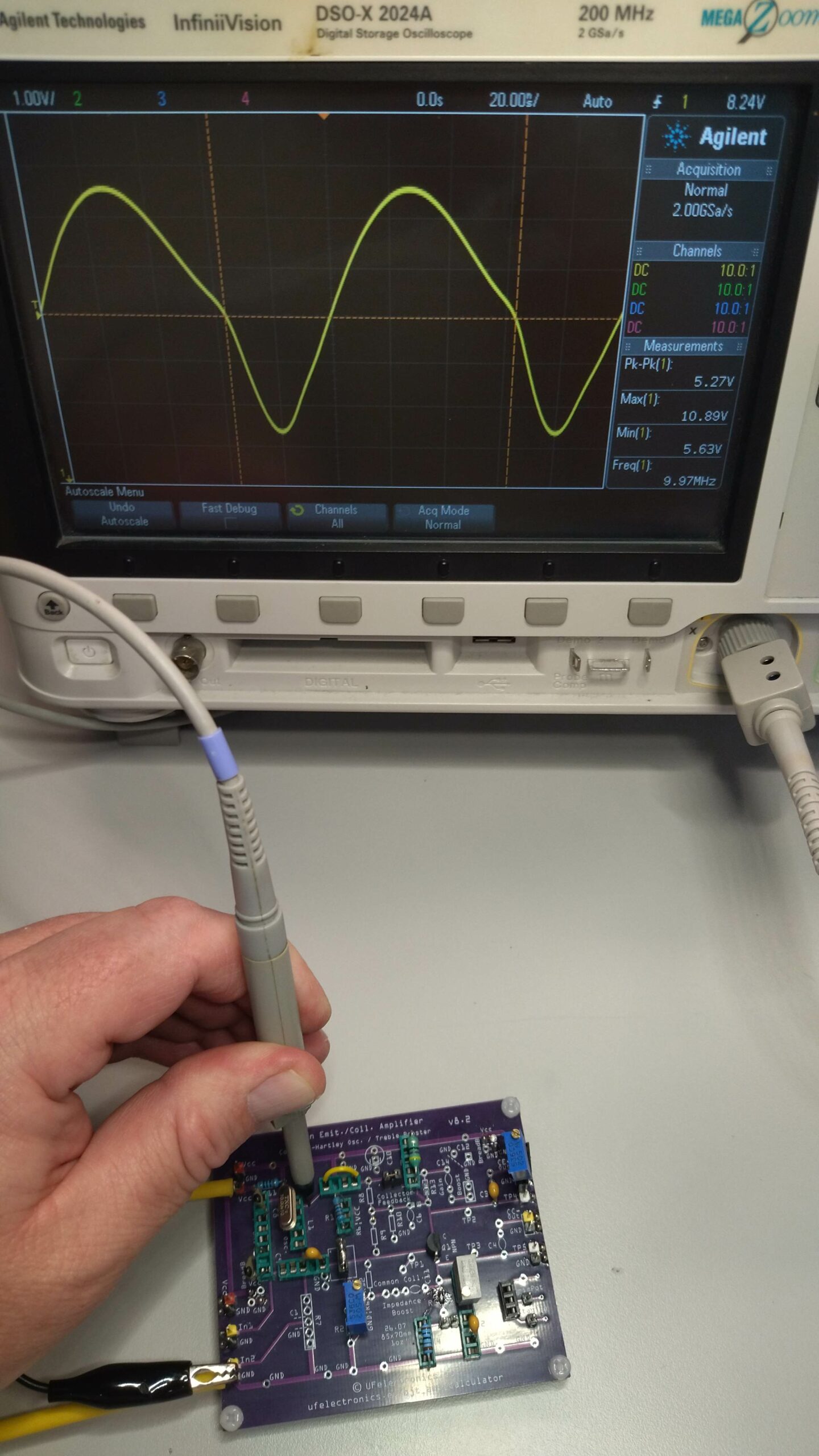
C1 only
- 10.89 V max
- 5.63 V min
- 5.27 Vpp
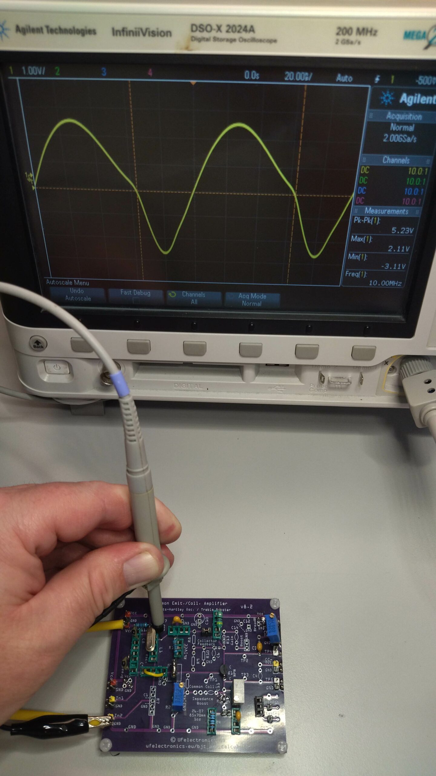
C5 only
- 2.11 V max
- -3.11 V min
- 5.23 Vpp
The difference is not the output amplitude, but the voltage swing across the crystal.
C5 significantly reduces the voltage applied to the crystal, which is preferable when avoiding unnecessarily high crystal drive.
Conclusion: C5 only.
Load
Effectively infinite load
- 7.08 Vpp
- -3.87 V to 3.17 V
- Measured after C3 at the output
1.3 kΩ load
- 2.12 Vpp with R5 = 200 Ω
- 4.74 Vpp with R5 = 30 Ω
450 Ω load
- Approximately 400 mVpp
The load has a significant effect on the output amplitude.
Vcc
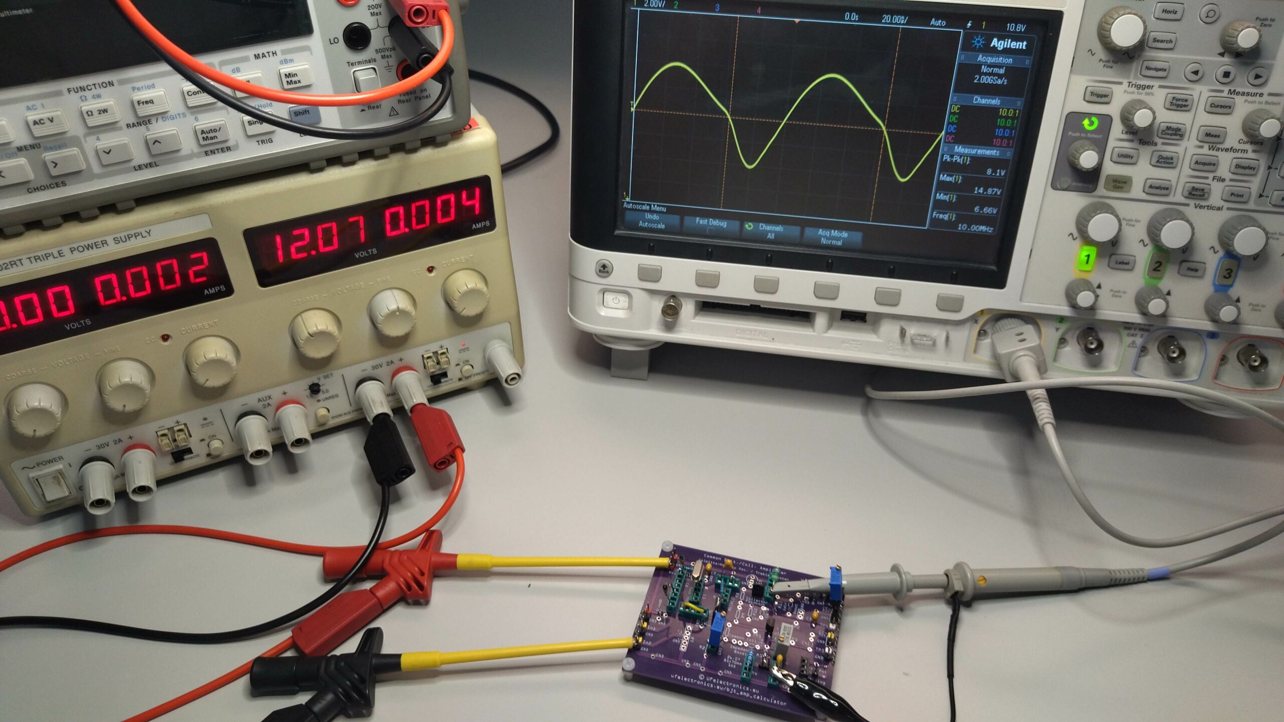
The circuit was designed for 9 V, but also operates at 12 V without any component adjustments.
At 12 V:
- 8.1 Vpp at the collector
Increasing Vcc increases the available output amplitude. R5 and the load can be used to control the output level.
Vcc Filtering – R11 + C7
This part did not perform as expected.
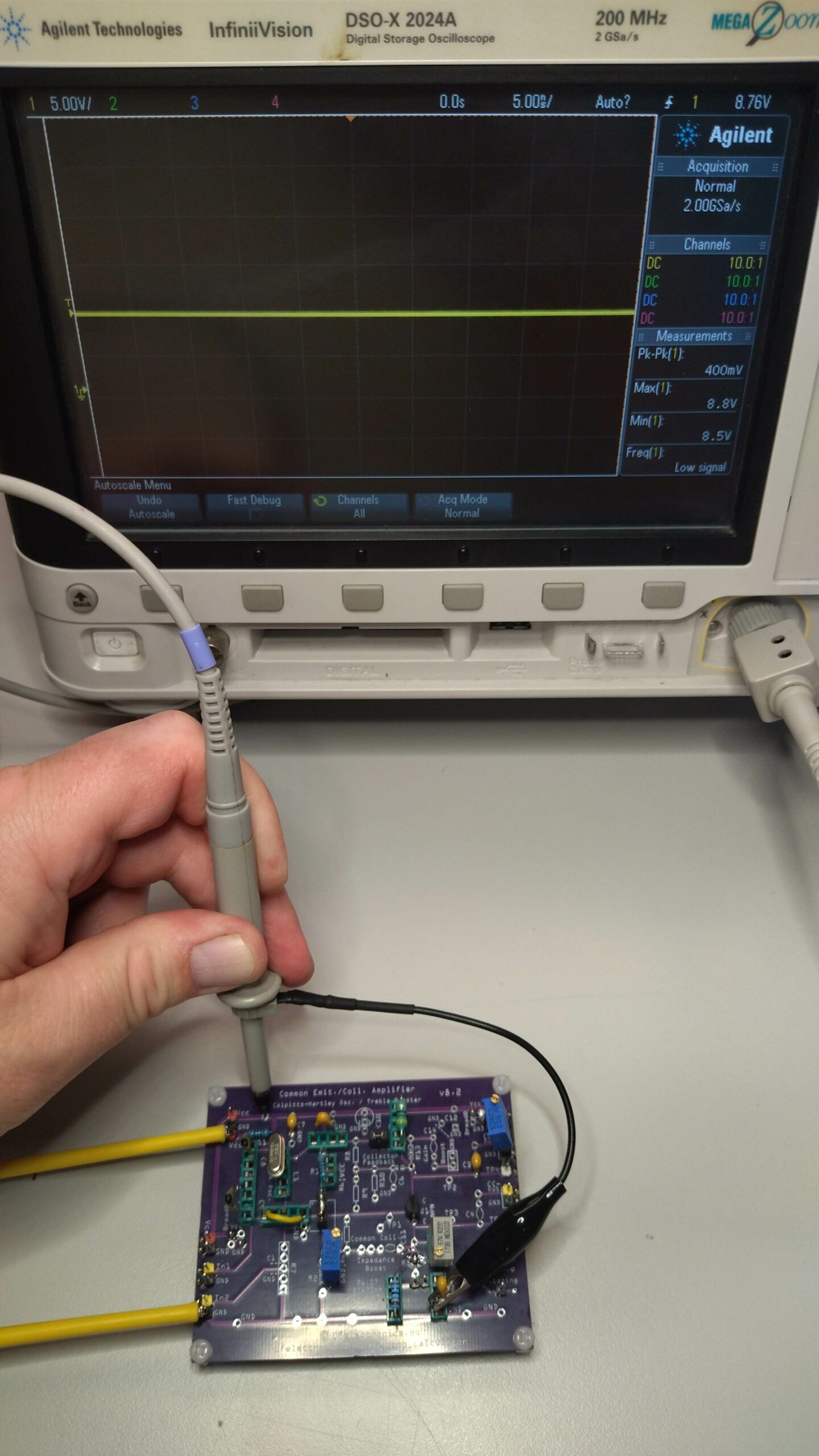
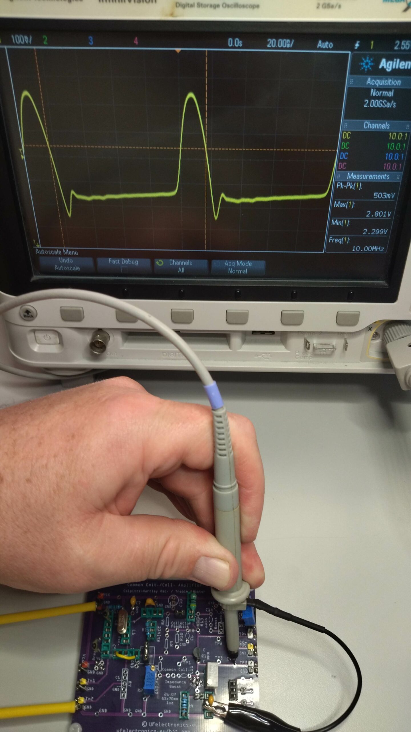
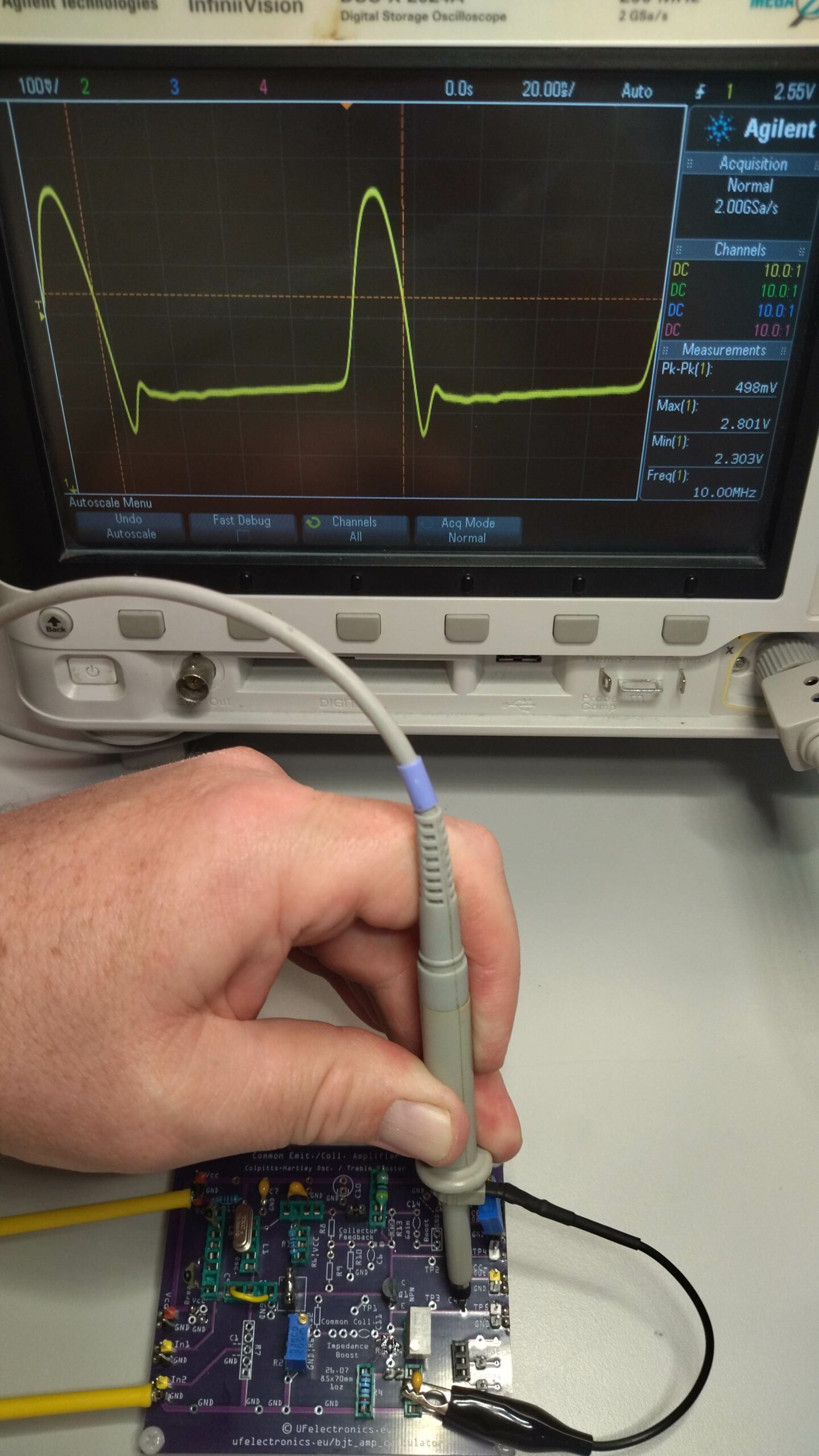
I measured approximately 400 mVpp on both sides of R11. The component values shown in the schematic therefore did not provide the intended filtering.
This section needs rework.
Current Consumption
Less than approximately 3 mA.
Conclusion
The oscillator works, and the measurements confirm that the schematic translates into a working build.
There is plenty of room for adjustment depending on the application. R5, C1/C5, the load and Vcc all have a noticeable influence on the output.
The Vcc filtering needs further work, but the basic circuit is operational.
You can now build the circuit yourself, knowing that it has been tested on the bench.