
Author: Andrew
-
A practical resource for professors and teachers in electronics engineering and STEM
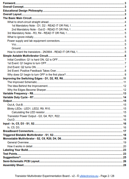
Full documentation for the Transistor Multivibrator Experimentation Board v2 is now available. It ended up being around 30 pages and doesn’t just contain schematics. It explains how the circuits actually work, what happens during the switching cycles, and how component values affect the behaviour. It includes complete, tested circuits for: * Astable Multivibrator * Bistable…
-

Annual Build Your Own UFO Convention
What topics and speakers would interest you? Location: Tentatively, the Tabernas Desert (Spain)… pending extraterrestrial approval. We will definitely hold the convention at a remote campsite with no light pollution. If you have a telescope, binoculars, an SDR, thermal camera, Geiger counter, magnetometer, or any other gadget that might detect something… unusual, bring it. You…
-
Differential Amplifier | 41-page Design Guide
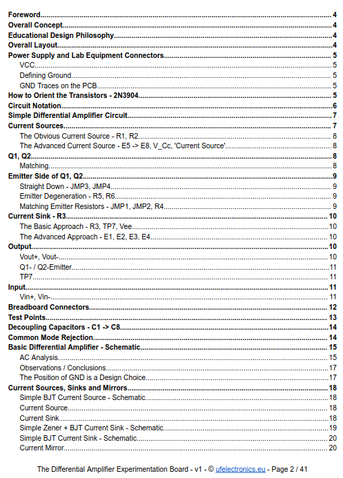
How do you go from a simple differential pair to the input stage of an operational amplifier? This 41-page guide is designed to answer exactly that question. The guide takes a progressive learning approach, starting with the simplest transistor differential amplifier and gradually introducing more advanced circuit techniques. The PDF includes: * Various differential amplifier…
-
Differential amplifiers are at the heart of analog electronics
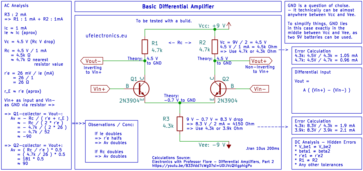
– But many beginners never get the opportunity to build one – That’s why I designed this basic differential amplifier as a learning exercise. The schematic is intended as a beginner-friendly introduction to differential amplifiers for anyone learning the fundamentals of analog electronics. The design is currently a theoretical first version. My next step is…
-
BJT Monostable Multivibrator – Schematic and Build
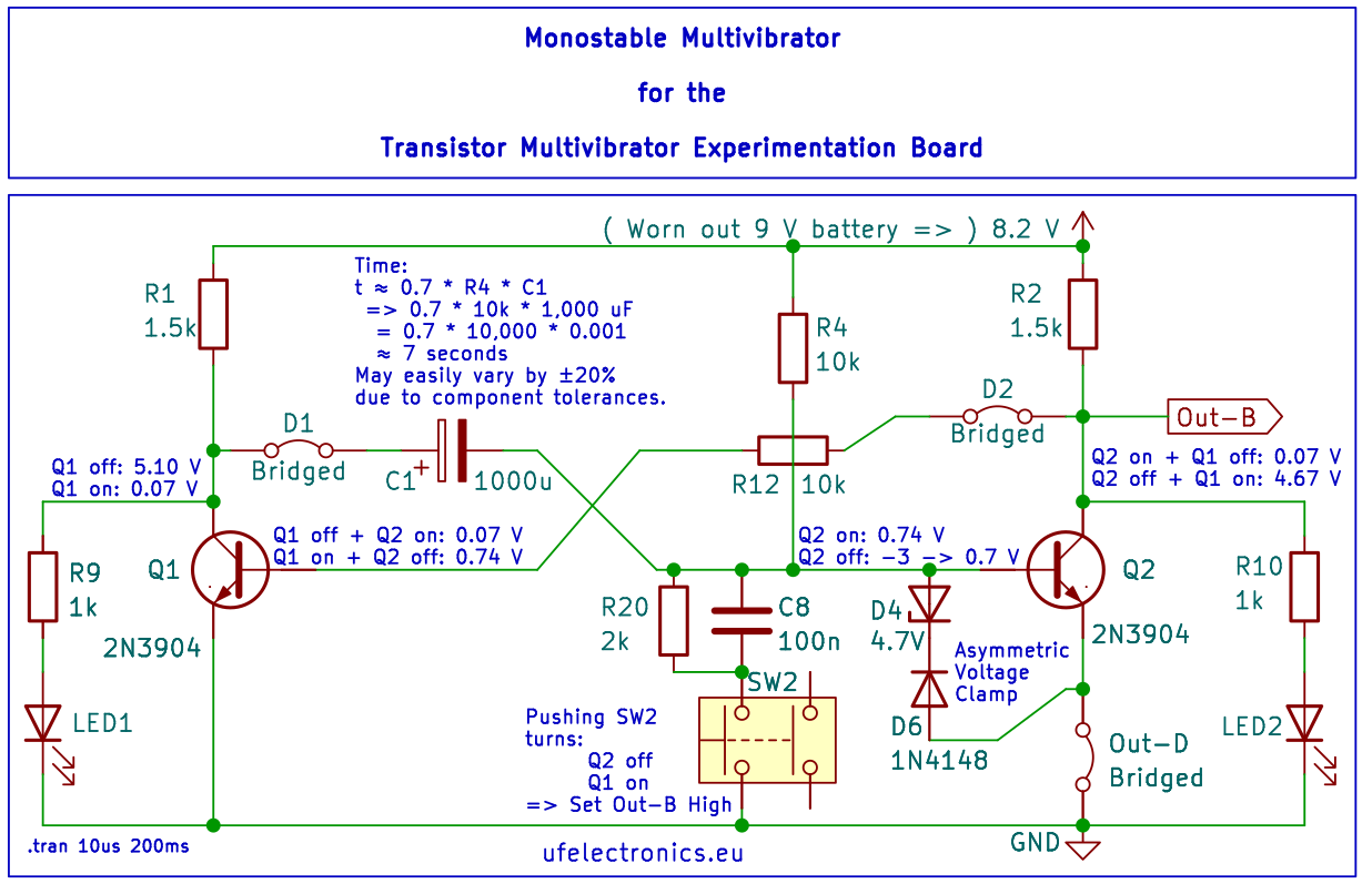
– and a Design Detail You Might Have Missed – When the trigger pulls the base of the second transistor low, the first transistor switches on and its collector falls rapidly from nearly Vcc to almost 0 V. BUT: The timing capacitor between the collector of Q1 and the base of Q2 cannot change its…
-
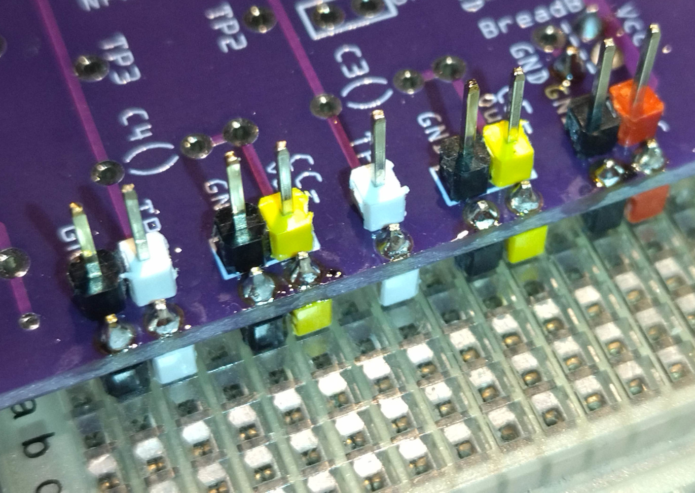
Extend experiments on to a breadboard
Extend the experiments on the input and the output side with the bottom faced pin headers with whatever on a breadboard. – And continue to use the pin headers on the top side for wires to whatever. You can even mount pin headers for the power rails on the breadboard.
-
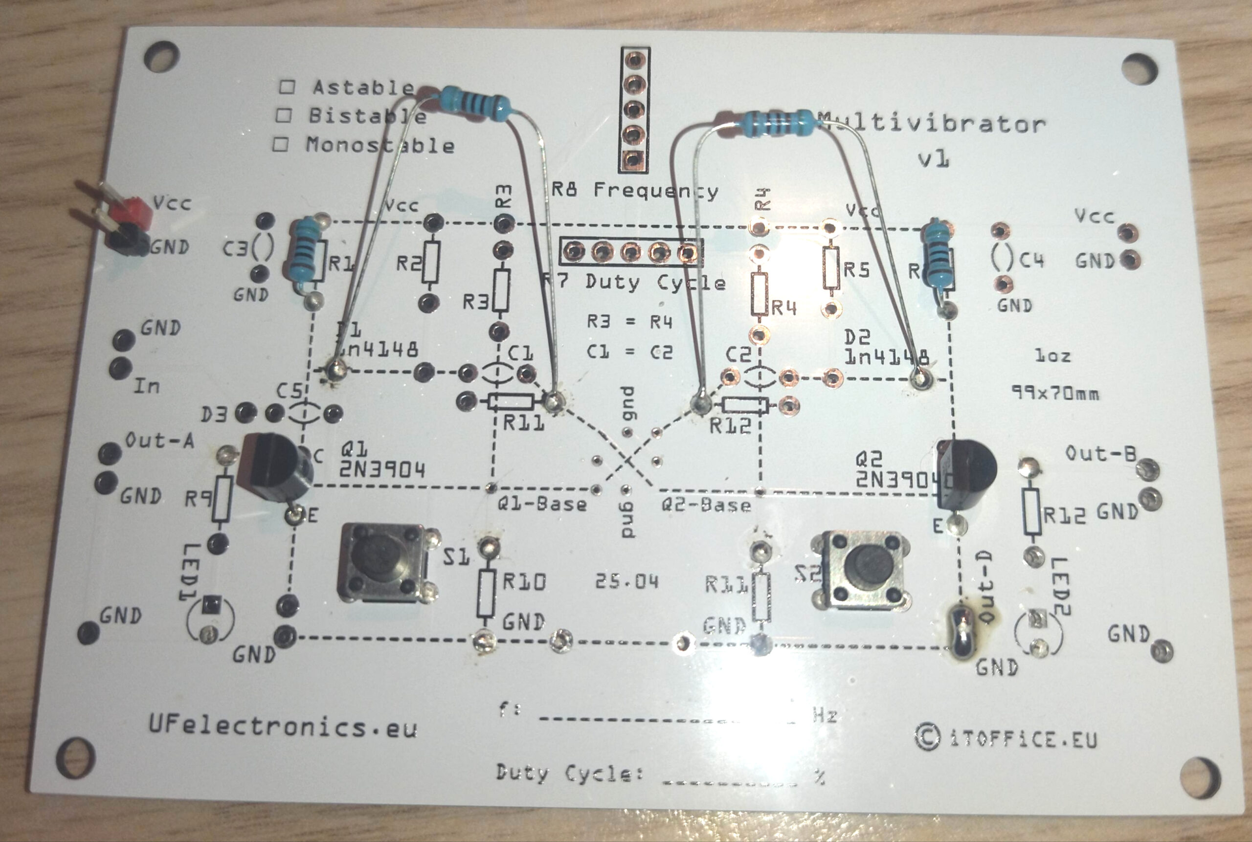
Triggered Bistable Multivibrator – Schematic and Build
PDF for downloading
-
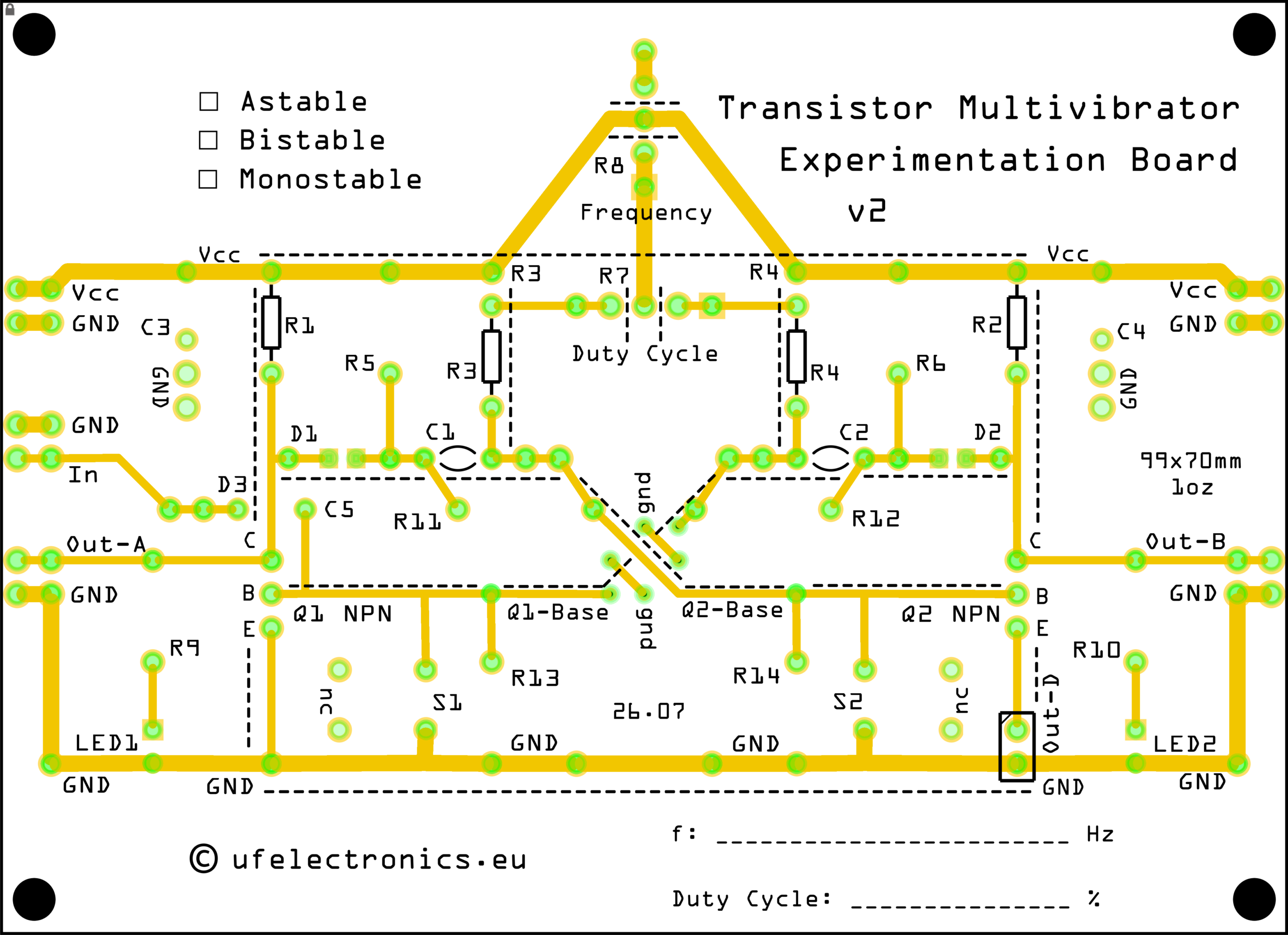
Schematic for a Simple 218 Hz Astable Multivibrator
Designed for the Transistor Multivibrator Experimentation Board, this circuit is a great introduction to transistor-based oscillators and multivibrator operation. BOM (Bill of materials) C1, C2: 100 nF (2x) JP1, JP2, Out-D1: Bridged (1x/3x) Q1, Q2: 2N3904 (2x) R1, R2: 2.2 kΩ (2x) R3, R4: 33 kΩ (2x) Version 2 of the PCB is coming this…
-
Version 8.2 of the Common Emitter/Collector Amplifier Board is public
– It’s about making experimentation easier – Version 8.2 adds several refinements: * Breadboard-friendly input and output pin header footprints * Breadboard power connection footprints on both the input and output sides * Optional jumper locations for greater configuration flexibility * A dedicated staging area for temporarily mounting trimmers using female pin sockets during circuit…
-
Dedicated Page for Shipping Rates
Shipping Rates Have Been Updated We’ve updated the shipping options at UFElectronics. You can now find the current shipping rates and available shipping methods for each supported country on our new Shipping Rates page. This means you can check the shipping cost before placing an order – no need to go through checkout just to…