Description
Precision Current Source for Analogue Electronics
The Symmetric Wilson Current Source Mirror is a compact experimentation board designed to explore one of the most useful transistor building blocks in analogue electronics: the Wilson current mirror.
Built around four matched PNP transistors (2N3906), this board provides an adjustable, high-performance current source that demonstrates how transistor feedback can dramatically improve current regulation compared to a simple current mirror.
Whether you are learning transistor circuits, designing analogue amplifiers, or experimenting with current sources and active loads, this board offers a practical way to understand the principles behind precision current generation.
Features
- Four 2N3906 PNP transistors arranged as a symmetric Wilson current mirror
- Adjustable output current using an onboard 10 kΩ trimmer
- Two emitter resistors for improved stability and experimentation
- Clearly accessible test points throughout the circuit
- Breadboard-friendly header connections
- Compact PCB suitable for laboratory work and education
What Can You Learn?
This board makes it easy to investigate topics such as:
- Current mirrors
- Wilson current mirrors
- Active current sources
- Active loads
- Transistor matching
- Current regulation
- Output compliance voltage
- Temperature effects
- Small-signal analogue design
- Differential amplifier current sources
- Precision bias circuits
Adjustable Output Current
The onboard trimmer adjusts the reference current flowing through the mirror.
Once set, the Wilson mirror reproduces this current at the output with significantly better accuracy than a simple two-transistor current mirror.
Students can directly observe:
- How the reference current determines the output current
- The effect of transistor β (gain)
- The improvement provided by feedback inside the Wilson mirror
- Current stability as output voltage changes
Breadboard Integration
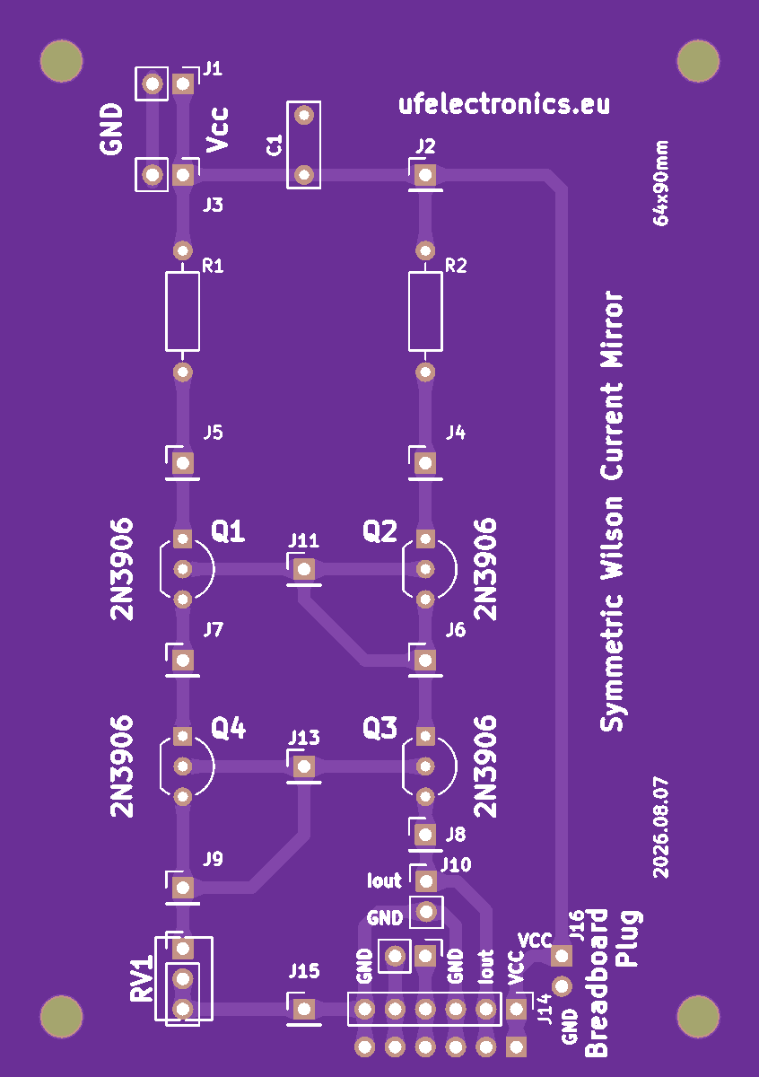
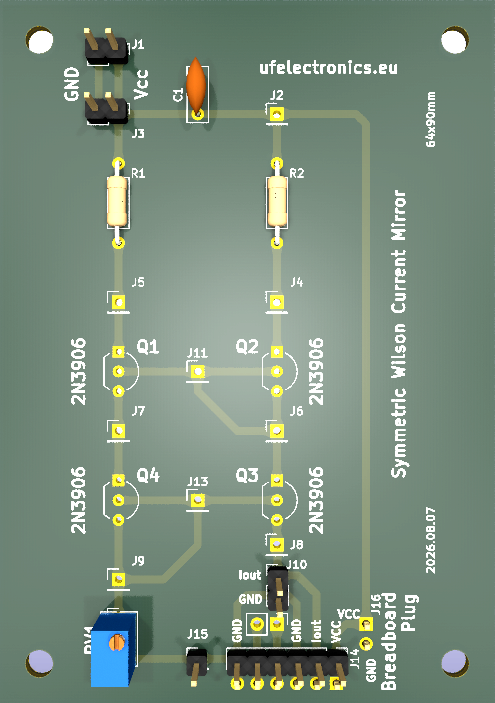
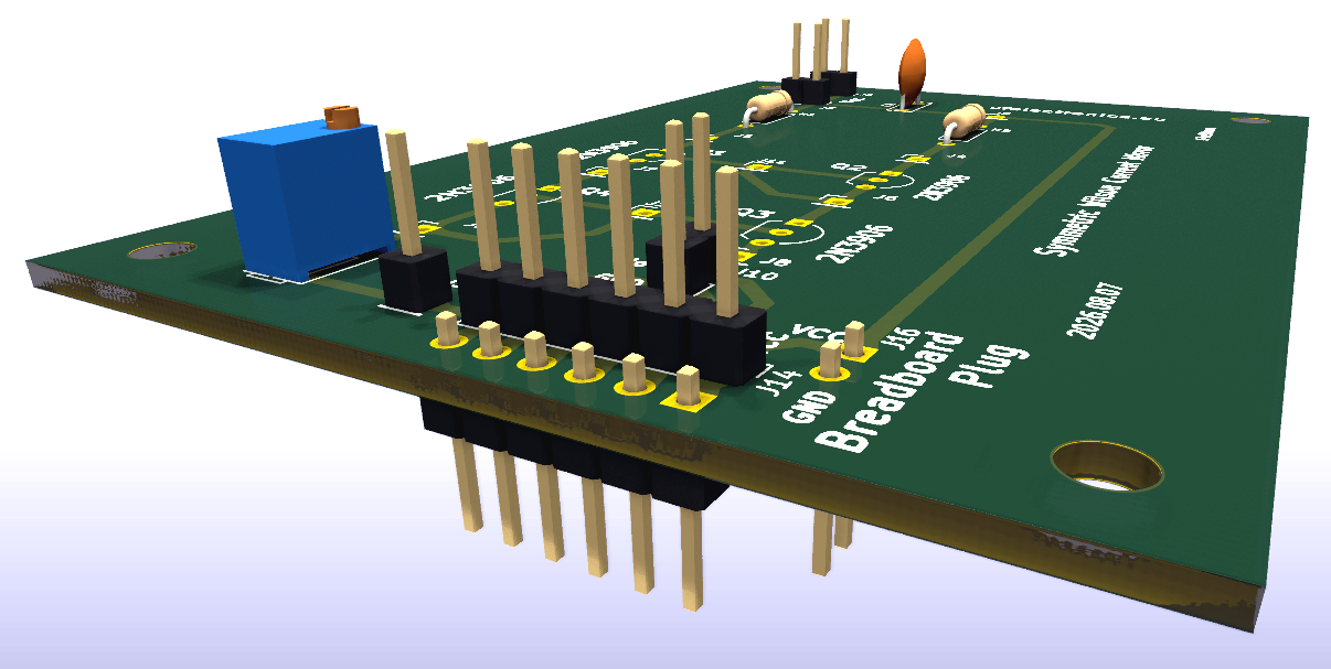
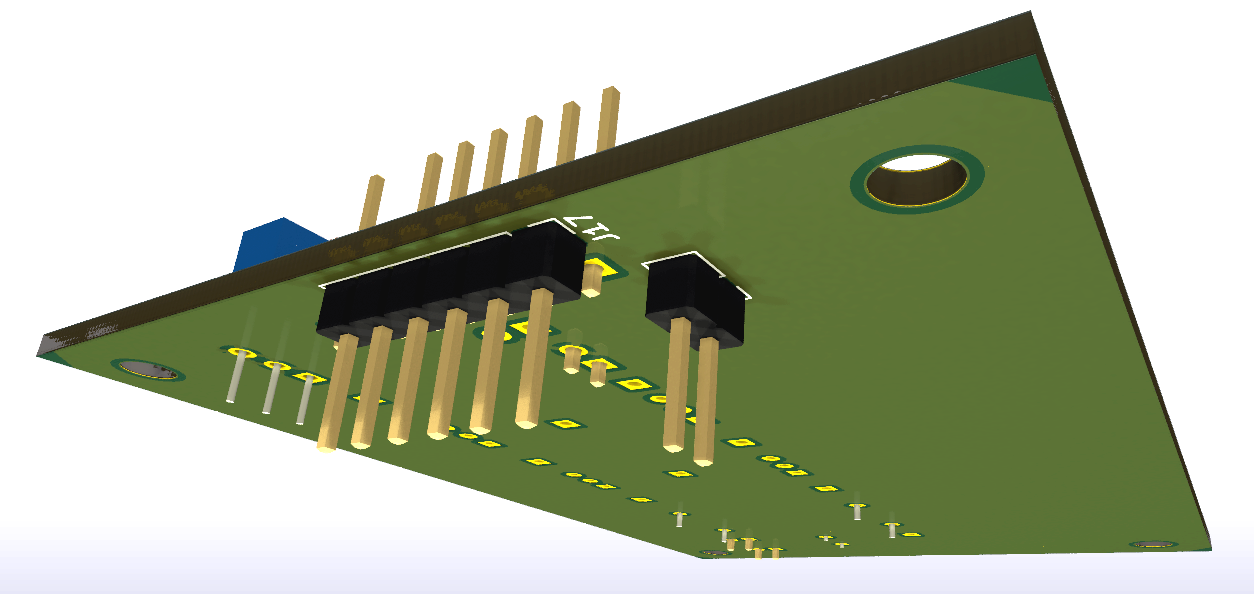
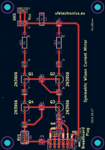
Along the southern edge of the PCB is a breadboard interface header.
This makes it easy to connect the current source into larger experiments, such as:
- Differential amplifiers
- Long-tailed transistor pairs
- Active loads
- Current sinks and sources
- Small signal amplifier stages
- Operational amplifier building blocks
Instead of wiring numerous jumper cables directly to transistor leads, all important signals are available from convenient header pins.
Accessible Connections
The board exposes the important connections needed for experimentation:
- VCC
- Ground / Reference Voltage
- Current Output (Iout)
Additional header pins make it simple to integrate the circuit with external breadboard projects.
Why a Wilson Current Mirror?
A simple current mirror works well for many applications but suffers from base current errors that reduce accuracy.
The Wilson current mirror introduces additional transistor feedback that greatly reduces these errors, resulting in:
- Better current accuracy
- Higher output resistance
- Improved regulation
- Better performance in analogue circuits
Because of these advantages, Wilson mirrors appear in many integrated circuits including operational amplifiers, voltage references, analogue filters, and precision bias networks.
Typical Experiments
Some suggested experiments include:
- Adjust the output current over its operating range.
- Measure the relationship between reference current and output current.
- Observe the effect of varying the output voltage.
- Compare the Wilson mirror with a simple two-transistor current mirror.
- Measure output resistance.
- Investigate transistor matching.
- Study temperature dependence.
- Use the board as the tail current source in a differential amplifier.
Designed for Education
Like all UF Electronics experimentation boards, this PCB is intended to help bridge the gap between circuit theory and practical electronics.
Instead of treating current mirrors as abstract schematic symbols, students can probe every node, make measurements, modify component values, and immediately observe how the circuit behaves.
It is equally suitable for:
- Electronics hobbyists
- Engineering students
- University laboratories
- Technical colleges
- Makers
- Professional engineers exploring analogue design
Specifications
| Feature | Description |
|---|---|
| Circuit Type | Symmetric Wilson Current Source Mirror |
| Transistors | 4 × 2N3906 PNP |
| Current Adjustment | 10 kΩ trimmer |
| Emitter Resistors | 2 × 18.2 Ω |
| Supply Voltage | User selectable |
| Output | Adjustable current source |
| Breadboard Interface | Yes |
| PCB | Through-hole components |
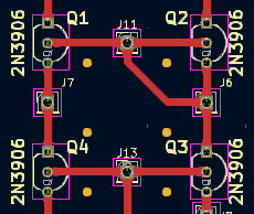
How to Orient the Transistors
Flat side to the left – Means emitter comes upwards, ‘north’ on the board.
Documentation is still under development
The downloadable documentation should in future includes:
- Complete schematic
- Circuit explanation
- Theory of operation
- Current mirror fundamentals
- Wilson mirror operation
- Example calculations
- Suggested laboratory experiments
- Measurement exercises
- Design notes